Questions on dying battery simulators

AniML

New member
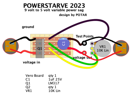
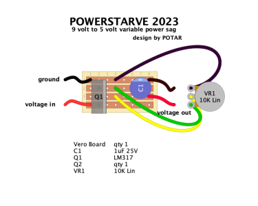
I've seen a few different basic circuit designs, including a simple pot between dc in and dc out (current drop), similarly a pot but adding a resistor to ground (the "Beavis" voltage divider) and one which employs an LM317.

I am interested to experiment with the first two. I am curious before I start, would combining the current drop with the voltage divider in series or parallel result in anything interesting ?

I can solder just fine, but my circuit designs/ understanding knowledge is minimal. Thanks
 
I have a variable voltage on my power supply. For blues or classic rock, a sagged overdrive/distortion is "okay." If the knob was more assesable I might use the function a bit more. I have also tried it on modulation effects, and it is a no-go. They just got noisy and added artifacts that were annoying like chirps.
 
Yah, reducing voltage works for drives - and especially well for vintage fuzz circuits - but not for comps or modulation, and especially not for anything digital.
I starve my fuzzes sometimes and it works nicely. Have an Alchemy Deadbat on my small board, which I believe is just a pot inside.
On my other board, the Voodoo Labs power supply underneath has two variable voltage outs. But I kinda prefer having a knob accessible on top.


I don't know enough to add anything constructive when it comes to circuit architecture. But years ago I read that a dying battery exhibits not just lower voltage but a change in resistance, and I believe there are voltage-drop boxes designed to duplicate that aspect also.
 
I haven't tried either.
 

Attachments

  • transistor-bias-pot.gif
    transistor-bias-pot.gif
    9.2 KB · Views: 0
  • powerstarve-potar-2023.png
    powerstarve-potar-2023.png
    119.7 KB · Views: 0
seems like a fun thing to try for dirt pedals. my fuzzface has an old 9v in there thats showing about 7.6v at the moment and it sounds glorious!
 
I'll need to look it up, but I remember there being one detail of implementing it that's important to get right lest you risk damaging your pedal.
 
On my other board, the Voodoo Labs power supply underneath has two variable voltage outs. But I kinda prefer having a knob accessible on top..

My Decibel 11 power supply was designed by the same engineers. Mine is in the same place. If it was easily assessable I would probably futz with mine more as well.
 
I'll need to look it up, but I remember there being one detail of implementing it that's important to get right lest you risk damaging your pedal.

Guessing maybe ensuring it is center negative?

I got the parts to start messing around it .. I also got my ToneBender MKii kit from General Guitar Gadgets, so I will soon be jumping back into the pedal-build rabbit hole after many years away. :)
 
Guessing maybe ensuring it is center negative?

I've been doing the research trying to figure out what it was. I think it had something to do with using a pot in series with the signal without a diode, which is not the optimal way to do it to begin with.

The best way to do it is the LM317 though, because that will lower both voltage and current. The series method won't lower current at all, which means it won't sound like a dying battery. The LM317 also allows you to increase voltage to the pedal, so there's more flexibility but also more risk if you don't know what you're doing
 
Ladies and Gentlemen introducing the Brown Note voltage attenuator. There's a 9V barrel jack in at the top and out at the bottom. There's an attenuator circuit with pot and banana jacks to connect my multimeter to measure output voltage.IMG20241227142910_BURST000_COVER.jpg - Click image for larger version  Name:	IMG20241227142910_BURST000_COVER.jpg Views:	0 Size:	56.7 KB ID:	6301291
 

Attachments

  • Brown-note.png
    Brown-note.png
    97.1 KB · Views: 0
Back
Top