You are using an out of date browser. It may not display this or other websites correctly.
You should upgrade or use an alternative browser.
You should upgrade or use an alternative browser.
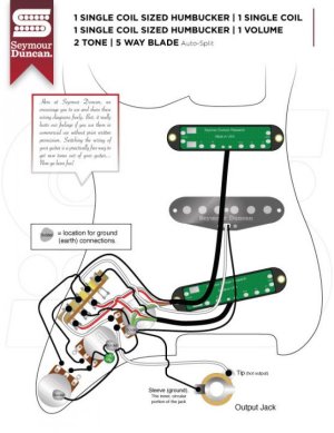
Really easy HSS Wiring question
- Thread starter Ronnie_Snow
- Start date
ThreeChordWonder
New member
I would say not for the bridge alone, position 1. In position 2, however, the bottom (tone) pot is linked across both the bridge and middle connections by the wiper, on the 5-way switch, so it then serves both bridge and middle pickups.
This is, I believe, in line with "traditional" Strat wiring, where there was no tone control for the bridge.
I also believe using the other side of the switch for the auto coil splits in positions 2 and 4 precludes wiring the bottom tone for the bridge and the middle for the middle and neck pickups. This is because the necessary jumper between the middle and neck pickup hot connections would "short" the switch, making both middle and neck active in positions 3, 4 and 5. A similar problem would arise wiring one tone just for the neck and the other shared by middle and bridge, I suspect.
Jack_TriPpEr
New member
ThreeChordWonder is correct in his assessment.
Even though it seems like a simple ask, unfortunately its not due to a normal 5 way switch being under-equipped for the task. A 5 way superswitch with its 2 extra poles is needed to get it done properly.
When usIng a normal 5 way switch, each solution has some tradeoffs. One popular option is to rewire so that its the bridge pickup that is connected to the lower tone pot, instead of the middle pickup. The tradeoff is that in Position 3 (middle pickup alone), there is no tone control in the circuit.
Jack_TriPpEr
New member
Another popular solution(and my personal prefrence) is to rewire so that there is just one Tone Control for the whole circuit, i.e. a Master Tone Control. The disconnected tone pot can remain in place just to keep appearances looking normal, or you can do something else with it. Examples: make it a Bass Cut control. Or make it a blend volume control so you can make the Neck pickup active in Positions 1 and 2. a.k.a. the Gilmour Mod.
Teleplayer
Active member
No. There is no bridge tone on the standard diagram. Its a difficulty to get two tone controls together with auto-split. The simplest option is to have 1 master tone control.. Otherwise you need a 4-pole superswitch to get a wiring scheme with 2 tone controls for 3 pickups.
Below is my attempted solution, but It actually doesn't work as drawn. Sorry!
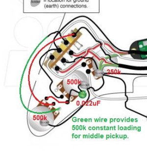
Below is my attempted solution, but It actually doesn't work as drawn. Sorry!

Last edited:
Jack_TriPpEr
New member
No. There is no bridge tone on the standard diagram. Its a difficulty to get two tone controls together with auto-split. The simplest option is to have 1 master tone control.. Otherwise you need a 4-pole superswitch to get a wiring scheme with 2 tone controls for 3 pickups.
Another alternative is my circuit below, which has the red wire to connect the tone control to the bridge pickup. Because of the green wire on my drawing, the tone for the middle pickup is as though its always set to "10".
i've never seen this idea before. could be pretty cool. Is the tone in Position 2 (Middle & Bridge) darker than notmal because both pups are being loaded?
Teleplayer
Active member
Unfortunately there is an error in my diagram. I used as similar scheme withe the unused side of the 5-way switch, but its going to cause a problem when you wire the tone control directly to the hot wires from the pickups. Sorry for my mistake.
Last edited:
ThreeChordWonder
New member
Okay...
So a "really easy" question turned into a major exercise in mental aerobics. Not that I'm complaining, becuase I've been OOW since this whole COVID thing started (thanks, big oil company that cut its CAPEX budget by 20% as a result), so mental exercises are welcomed.
Anyway....
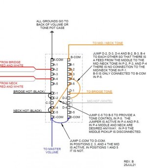
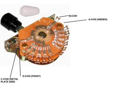
I sat down this morning after the dog woke me up at six and started sketching based on a Fender 5-way "super-switch" (see photo).
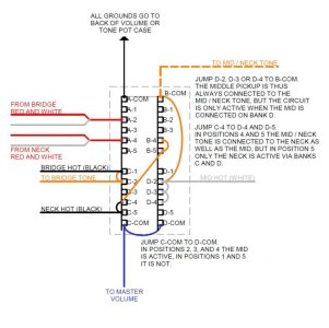
In my wiring diagram. I've drawn the switch as if looking at it mounted on the pickguard, and you are looking at the underside of the pickguard, as you would be soldering the thing up. So Bank A is on the metal side plate side, nearest the guitar neck, with the output lug also nearest to the guitar neck. Bank C C is the bottom left, nearest the metal side plate with the common or output lug to the bottom left. I think you can figure out for yourselves where banks B and D are for yourself, if not please put down the soldering iron and step away from the work bench.
Pickup Selection:
Bank C is used to control the outputs to the volume pot. In positions 1 (bridge only) and 2 (bridge and middle) the bridge hot (black on an S-D humbucker) is connected via C-1 and C-2 to C-COM, then to the volume pot. The neck pickup is not connected at all. In positions 4 (middle and neck) and 5 (neck only) the neck hot (black) is connected via C-4 and C-5 to C-COM. In position 3, neither the neck or bridge are connected at all.
To control the middle pickup I've used Bank D. The middle pickup hot is connected to D-2, D-3 and D-4 then to D-COM. D-COM jumps to C-COM. So in position 1 (bridge only) and position 5 (neck only) the middle pickup hot is completely disconnected as it should be. In all three other positions the middle pickup is hot. You only get bridge plus middle in position 2, however, as the bridge is only connected in positions 1 and 2. You don't get the middle in position 1 because the middle hot isn't connected to position 1. Similar logic applies to positions 4 and 5.
For all pickups, the grounds go to the backs of the volume or tone pots - green and bare for the humbuckers, black for the single coil.
Auto Coil Splitting:
For auto coil splitting I've used Bank A. I selected Bank A simply because it makes wiring up the middle and neck tone control neater. The red and white "middle" wires for the bridge pickup are connected to A-2, the red and white for the neck pickup to A-4. A-COM is connected to ground, so in positions 2 and 4 only the red and white wires for the bridge and neck pickups, respectively, get grounded and so the pickups get coil split.
Bridge Tone Control:
The bridge tone pot is easy. Just wire it in parallel to the bridge hot input on the switch, job done. It works in positions 1 and 2, where it is needed, and since the pickup isn't connected in positions 3, 4 and 5, it doesn't do anything to the overall output in those three positions.
Middle and Neck Tone Control:
This is the tricky bit.
We need to connect the middle and neck to a common tone pot without creating a short on the switch that makes the middle or neck permanently active.
The way I came up with is as follows. There may be other / better ways, but I THINK this works.
The middle pickup is permanently connected to the middle/neck tone pot via a jumper from D-2, D-3 and/or D-4 to B-COM and then out to the tone pot. Middle tone control only comes into play, however, when the middle pickup is active via bank D and the jumper to Bank B, i.e. positions 2,3 and 4, i.e. when it's wanted. In positions 1 and 5 the middle pickup connection is dead, so it doesn't contribute to the overall tone (I think).
The neck pickup is connected to the middle/ neck tone via a jumper from C-4 and/or C-5 to B-4 and/or B-5 (both 4 and 5 must be connected at each end). In positions 4 and 5 the neck pickup is activated via Bank B, in positions 1, 2 and 3 on Bank B it's disconnected.


Last edited:
ThreeChordWonder
New member
PS one mod might be to wire the D-2 to B-COM jumper from D-COM to B-COM instead. That way the mid/ neck tone only works with the neck connected via Bank D. In positions 1 (bridge only) and 5 (neck only) the middle wouldn't be connected to its tone pot at all.
ThreeChordWonder
New member
PPS the humbucker greens and bares plus the mid black all get grounded. The rest of the wiring is standard strat
Ronnie_Snow
Member
Thats getting too complicated for me. I think I'll just throw in a volume push pull pot in and hook up both the bridge and neck pup and then just do the normal bridge pup to tone pot mod...
Jack_TriPpEr
New member
Okay...
So a "really easy" question turned into a major exercise in mental aerobics. Not that I'm complaining, becuase I've been OOW since this whole COVID thing started (thanks, big oil company that cut its CAPEX budget by 20% as a result), so mental exercises are welcomed.
Anyway....
I sat down this morning after the dog woke me up at six and started sketching based on a Fender 5-way "super-switch" (see photo).
In my wiring diagram. I've drawn the switch as if looking at it mounted on the pickguard, and you are looking at the underside of the pickguard, as you would be soldering the thing up. So Bank A is on the metal side plate side, nearest the guitar neck, with the output lug also nearest to the guitar neck. Bank C C is the bottom left, nearest the metal side plate with the common or output lug to the bottom left. I think you can figure out for yourselves where banks B and D are for yourself, if not please put down the soldering iron and step away from the work bench.
Pickup Selection:
Bank C is used to control the outputs to the volume pot. In positions 1 (bridge only) and 2 (bridge and middle) the bridge hot (black on an S-D humbucker) is connected via C-1 and C-2 to C-COM, then to the volume pot. The neck pickup is not connected at all. In positions 4 (middle and neck) and 5 (neck only) the neck hot (black) is connected via C-4 and C-5 to C-COM. In position 3, neither the neck or bridge are connected at all.
To control the middle pickup I've used Bank D. The middle pickup hot is connected to D-2, D-3 and D-4 then to D-COM. D-COM jumps to C-COM. So in position 1 (bridge only) and position 5 (neck only) the middle pickup hot is completely disconnected as it should be. In all three other positions the middle pickup is hot. You only get bridge plus middle in position 2, however, as the bridge is only connected in positions 1 and 2. You don't get the middle in position 1 because the middle hot isn't connected to position 1. Similar logic applies to positions 4 and 5.
For all pickups, the grounds go to the backs of the volume or tone pots - green and bare for the humbuckers, black for the single coil.
Auto Coil Splitting:
For auto coil splitting I've used Bank A. I selected Bank A simply because it makes wiring up the middle and neck tone control neater. The red and white "middle" wires for the bridge pickup are connected to A-2, the red and white for the neck pickup to A-4. A-COM is connected to ground, so in positions 2 and 4 only the red and white wires for the bridge and neck pickups, respectively, get grounded and so the pickups get coil split.
Bridge Tone Control:
The bridge tone pot is easy. Just wire it in parallel to the bridge hot input on the switch, job done. It works in positions 1 and 2, where it is needed, and since the pickup isn't connected in positions 3, 4 and 5, it doesn't do anything to the overall output in those three positions.
Middle and Neck Tone Control:
This is the tricky bit.
We need to connect the middle and neck to a common tone pot without creating a short on the switch that makes the middle or neck permanently active.
The way I came up with is as follows. There may be other / better ways, but I THINK this works.
The middle pickup is permanently connected to the middle/neck tone pot via a jumper from D-2, D-3 and/or D-4 to B-COM and then out to the tone pot. Middle tone control only comes into play, however, when the middle pickup is active via bank D and the jumper to Bank B, i.e. positions 2,3 and 4, i.e. when it's wanted. In positions 1 and 5 the middle pickup connection is dead, so it doesn't contribute to the overall tone (I think).
The neck pickup is connected to the middle/ neck tone via a jumper from C-4 and/or C-5 to B-4 and/or B-5 (both 4 and 5 must be connected at each end). In positions 4 and 5 the neck pickup is activated via Bank B, in positions 1, 2 and 3 on Bank B it's disconnected.
Unfortunately because the Middle pickup Hot wire has a hardwire connection to the Neck/Middle Tone pot via B Common, Position 5 would be both Neck and Middle.
Also, there is no need to run the Bridge Tone pot connection through the 5 way switch. Simply run Bridge Hot wire to the Tone pot, and then from Bridge Tone pot to to Bank C 1 (and then jumper that to Bank C 2 as you have it). The current extra wire run to the 5 way and then out to the Bridge Tone pot creates an opportunity for RF/60 cycle noise to get into the circuit.
There is a typo in your note in the upper right corner. It talks about a jumper from C4 to D4 and D5, but it means to say jump C4 to B4 and B5.
I've seen a wiring diagram online where someone figured out how to do this with a 5 way superswitch. Cannot remember if i downloaded it or not. I'll look my collection to verify. But won't post it unless you ask, since you may be enjoying the mental exercise of trying to figure this out.
Jack_TriPpEr
New member
There is a typo in your note in about the junper btw D 2-4. It uses an "or" in the description but should be an "and".
Jack_TriPpEr
New member
ThreeChordWonder, the other diagram that does this that i mentioned, also found a way to have only 1 tone pot active in Position 2. You should be shooting for that as well in your design.
ThreeChordWonder
New member
Unfortunately because the Middle pickup Hot wire has a hardwire connection to the Neck/Middle Tone pot via B Common, Position 5 would be both Neck and Middle.
Are you sure? The middle hot isn't connected to D-5, so in P-5, with D-5 only connected to D-COM there's not path from the middle pickup to B or C?
Also, there is no need to run the Bridge Tone pot connection through the 5 way switch. Simply run Bridge Hot wire to the Tone pot, and then from Bridge Tone pot to to Bank C 1 (and then jumper that to Bank C 2 as you have it). The current extra wire run to the 5 way and then out to the Bridge Tone pot creates an opportunity for RF/60 cycle noise to get into the circuit.
Agreed, but if RF is getting in, it's getting in. We're talking maybe an extra inch and a half of wire here.
[/QUOTEQUOTE=Jack_TriPpEr;n6098837]
There is a typo in your note in the upper right corner. It talks about a jumper from C4 to D4 and D5, but it means to say jump C4 to B4 and B5.
[/QUOTE]
Seen and noted.
I've seen a wiring diagram online where someone figured out how to do this with a 5 way superswitch. Cannot remember if i downloaded it or not. I'll look my collection to verify. But won't post it unless you ask, since you may be enjoying the mental exercise of trying to figure this out.
Comments appreciated. Thanks
Jack_TriPpEr
New member
Are you sure? The middle hot isn't connected to D-5, so in P-5, with D-5 only connected to D-COM there's not path from the middle pickup to B or C?
Agreed, but if RF is getting in, it's getting in. We're talking maybe an extra inch and a half of wire here.
[/QUOTEQUOTE=Jack_TriPpEr;n6098837]
There is a typo in your note in the upper right corner. It talks about a jumper from C4 to D4 and D5, but it means to say jump C4 to B4 and B5.
I'm sure about the first part regarding the Middle pickup being active in Position 5 given the current design.
Regarding the current Bridge tone pot wiring: i've read where one guy who has much more experience in trying to eliminate RF interface than me, that anywhere where is more than 1 inch of unshielded wire is a spot where RF could become a problem. Agreed i can't guarantee it will be a problem in this case because i think that is dependent on how well shielded the guitar is already and the wiring in the building(s) where the guitar will be used mostly. But, i'm just pointing out good practice about minimizing unshielded cable runs.
Jack_TriPpEr
New member
Hmmm... i drop my certainty on the Middle pickup behavior down to "pretty sure" for now. When i grt home i'll sketch out the eletrical flow from all the active grounds to hot on paper and doublecheck.
ThreeChordWonder
New member
Jack_TriPpEr
New member
How about this version?
I think I've ironed out all the shorts.
The bridge tone now works only in P-1. The neck/ middle tone takes over in all other positions.
This latest design seems to resolve the earlier problem of the Middle pickup being active in Position 5. Nice work.
But i also believe the new design for Position 2 causes none of the Bridge pup's signal to run through the active tone pot - only the Middle pickup's trebel frequencies get cut by the active tone pot (neck/middle) in Position 2.
ThreeChordWonder
New member
^As I said, the bridge tone only works in P-1, in all other positions the other tone pot takes over.
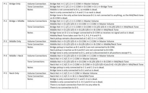
In P-2 the bridge and middle are connected to the neck/mid tone:
Bridge Hot >> C-2 >> C-COM >> D-COM >> D-2/3/4 >> B-2/3/4 >> B-COM >> Tone Pot
Mid Hot >> D-2/3/4 >> B-2/3/4 >> B-COM.
If you want the Bridge Tone to work in both "Bridge on" positions, connect the bridge tone across C-1or C-2, which are linked so it doesn't matter which.
By extension, if that works, you could connect the mid/neck tone to C-4/5 and D-2/3/4 and do away with Bank B entirely. I'll have to look at that later today.
Similar threads
- Replies
- 49
- Views
- 979
- Replies
- 12
- Views
- 254

