This is a spin-off from my recent Vintage SD Pickup Ident thread: "Vintage SD Pickup Identification"
I welcome any comments about the circuit layout and components of this vintage HSS Super Strat configuration, featuring 3 Mini Switches, mounted in an old Fender American Standard Plus Stratocaster. A break in the circuit kept me from hearing how the instrument sounds prior to removing the strings. While the pick guard is off for the circuit repair, I want to document the circuit and verify that it is configured "correctly".
Initial topics of interest:
manner in which the pickups are connected to the mini switches
configuration and function of the concentric stacked Tone potentiometer(s)
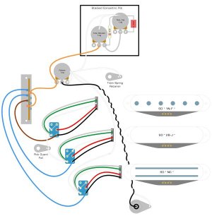
Following is an evaluation of the circuit together with a schematic - both of which were posted earlier in the PU ID thread.
** === Vintage HSS Super Strat Circuit & Components === **
There is a single tone control, consisting of a concentric pair of stacked potentiometers (of unknown values). I THINK the wipers of both pots turn simultaneously. There is a 022k cap between the "Grd" terminal of the outer pot (opposite end of shaft) and its case. There is a) a Jumper between the "Output" terminal of the outer pot and the "Grd" terminal of the inner pot; and an 82k Ω resistor between the "Grd" terminal of the inner pot and the case of the outer pot.
The 5-Way pickup combinations appear conventional:
.
.
All three of the DPDT mini switches are ON-ON. (The switches are rated 5A,120VAC)
For discussion purposes, let's describe terminal positions and activation sequences as follows:
.
.
All three pickups are wired to their switches in effectively the same manner (SW2 has White soldered to T4 instead of T2, but T4 & T2 are jumpered together)
.
I am new to puzzling out guitar circuit layouts. What I think the mini switches are doing is as follows:
.
For SW1, SW2 & SW3
.
.
Now - if this evaluation of the current layout is correct, is it customary or contradictory to:

I welcome any comments about the circuit layout and components of this vintage HSS Super Strat configuration, featuring 3 Mini Switches, mounted in an old Fender American Standard Plus Stratocaster. A break in the circuit kept me from hearing how the instrument sounds prior to removing the strings. While the pick guard is off for the circuit repair, I want to document the circuit and verify that it is configured "correctly".
Initial topics of interest:
manner in which the pickups are connected to the mini switches
configuration and function of the concentric stacked Tone potentiometer(s)
Following is an evaluation of the circuit together with a schematic - both of which were posted earlier in the PU ID thread.
** === Vintage HSS Super Strat Circuit & Components === **
There is a single tone control, consisting of a concentric pair of stacked potentiometers (of unknown values). I THINK the wipers of both pots turn simultaneously. There is a 022k cap between the "Grd" terminal of the outer pot (opposite end of shaft) and its case. There is a) a Jumper between the "Output" terminal of the outer pot and the "Grd" terminal of the inner pot; and an 82k Ω resistor between the "Grd" terminal of the inner pot and the case of the outer pot.
The 5-Way pickup combinations appear conventional:
.
P1: Neck
P2: Neck & Middle
P3: Middle
P4: Middle & Bridge
P5: Bridge
.P2: Neck & Middle
P3: Middle
P4: Middle & Bridge
P5: Bridge
.
All three of the DPDT mini switches are ON-ON. (The switches are rated 5A,120VAC)
For discussion purposes, let's describe terminal positions and activation sequences as follows:
.
T1 -- T4 Outputs (Toggle BCK)
T2 -- T5 Inputs
T3 -- T6 Outputs (Toggle FWD)
SWn FWD:.. T2 w/ T3 ..and.. T5 w/ T6
SWn BCK:.. T2 w/ T1 ..and.. T5 w/ T4
.T2 -- T5 Inputs
T3 -- T6 Outputs (Toggle FWD)
SWn FWD:.. T2 w/ T3 ..and.. T5 w/ T6
SWn BCK:.. T2 w/ T1 ..and.. T5 w/ T4
.
All three pickups are wired to their switches in effectively the same manner (SW2 has White soldered to T4 instead of T2, but T4 & T2 are jumpered together)
.
I am new to puzzling out guitar circuit layouts. What I think the mini switches are doing is as follows:
.
For SW1, SW2 & SW3
.
Toggle position "FWD": Black-&-Red-to Coils;..White-&-Green-to-Grd [BOTH Coils operating IN PARALLEL ?]
Toggle position "BCK": Red-&-White-to-Coils;..White-&-Green-to-Grd [ONE (secondary) Coil operating ALONE ?]
.Toggle position "BCK": Red-&-White-to-Coils;..White-&-Green-to-Grd [ONE (secondary) Coil operating ALONE ?]
.
Now - if this evaluation of the current layout is correct, is it customary or contradictory to:
- wire the coils of Humbuckers and Stacks in parallel, instead of in series?
- coil-split Humbuckers and Stacks by selecting the secondary winding and cutting out the primary winding ?