This is my first guitar wiring effort, feel pretty burnt out spending hours watching videos and reading articles on how switch wiring works, and then applying that to my situation.
I apparently have a crapped out 5-way switch on my 80's Japanese import fat strat type guitar. Unfortunately, I opted for an Oak Grigsby 5-way, 2-pole switch, because I thought it would give me more options down the road for wiring if I wanted to play with different configurations. I say "unfortunately" not because it's a bad switch, but rather because it's near impossible to find any schematic using this switch which has a total of 12 connector options. So I had to try to understand the logic behind how switches work, then apply that to this switch, and I'm not at all sure I got it right because the logic of this switch seems different with its 6 terminals to a side (or stage?) rather than 4 terminals. I finally realized I was not going to know what I don't know unless I tried to diagram it and see what I'm doing wrong.
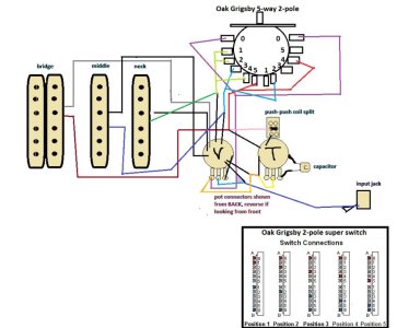
I've desoldered and removed the old switch, and need to wire up the new one. i'm hoping I won't need to re-do any of the other soldering, everything shown in the diagram is already wired up EXCEPT the 5-way switch.
The actual wires are all black or white, I did them in different colors in diagram for ease of following the paths they take, or will take. Another confusion is that I do not see 4 wires from the humbucker, but only 3 (not counting the bare wire to ground), so I'm really confused how it works with 3 rather than 4 wires -- one to tone, one to push-pull coil split, 1 to 5-way switch. But oh, well, it seems to work.
The logic of the diagram below, in my mind, is that in position 1, I have the neck pup going to terminal 1 on the left stage of the Oak Grigsby switch which I understand should suffice. Similarly, I have middle going to terminal 3 on that stage, and the bridge going to terminal 5 on that stage, then terminal 0 of that stage goes to volume. My understanding is, if I did nothing else, this would give me a "standard" 3-way switch effect, with no sound on positions 2 and 4.
In order to get pickup combinations in positions 2 and 4, I plan to split the neck wire twice and send one of those to terminal 2 and the other to terminal 4 on the left side, then split the middle and send that to terminal 2 of the right side and split the bridge and send that to terminal 4 of the right side, then send terminal 0 of the right stage to volume, too (or I guess I could wire the terminal 0's together? I just realized that may be the better approach). Anyway, my understanding was this would give me neck & middle in position 2 and then neck and bridge in position 4 (rather than middle and bridge as would be more standard).
This all hinges on my understanding that this Oak Grigsby 5-way, 2-pole switch (unlike any other 5-way switch I've found) has two stages/poles each with SIX terminals, so that one terminal from each stage can be dedicated to one switch position. Oh, I had thought instead of splitting the wires from the pups to send them to more than one terminal doing terminal to terminal wiring (so left terminal 1, from neck, could then be wired to left terminal 2 and left terminal 4 so that neck would be active in those positions as well, and then left terminal 3 (from bridge) could be wired to right terminal 2, so that position would be neck and middle. Then left terminal 5 (from bridge) would be wired to right terminal 4 so that position 4 has the bridge active, too. Now that I write it out, that seems to match more of what I see than splitting wires from the pickups themselves. Does that sound right?
Lastly, if anyone can steer me to some GOOD resources on this type of Oak Grigsby 5-way, 2-pole switch I'd appreciate it. The only thing that came with it was a diagram which simply shows which terminals are connected to terminal 0 in each of the 5 positions, which I can see just looking at the switch itself since it's open. I'd really like to see anyone else with a wiring diagram using this switch for HSS or even SSS set up.
Thanks,
Ken
I apparently have a crapped out 5-way switch on my 80's Japanese import fat strat type guitar. Unfortunately, I opted for an Oak Grigsby 5-way, 2-pole switch, because I thought it would give me more options down the road for wiring if I wanted to play with different configurations. I say "unfortunately" not because it's a bad switch, but rather because it's near impossible to find any schematic using this switch which has a total of 12 connector options. So I had to try to understand the logic behind how switches work, then apply that to this switch, and I'm not at all sure I got it right because the logic of this switch seems different with its 6 terminals to a side (or stage?) rather than 4 terminals. I finally realized I was not going to know what I don't know unless I tried to diagram it and see what I'm doing wrong.
I've desoldered and removed the old switch, and need to wire up the new one. i'm hoping I won't need to re-do any of the other soldering, everything shown in the diagram is already wired up EXCEPT the 5-way switch.
The actual wires are all black or white, I did them in different colors in diagram for ease of following the paths they take, or will take. Another confusion is that I do not see 4 wires from the humbucker, but only 3 (not counting the bare wire to ground), so I'm really confused how it works with 3 rather than 4 wires -- one to tone, one to push-pull coil split, 1 to 5-way switch. But oh, well, it seems to work.
The logic of the diagram below, in my mind, is that in position 1, I have the neck pup going to terminal 1 on the left stage of the Oak Grigsby switch which I understand should suffice. Similarly, I have middle going to terminal 3 on that stage, and the bridge going to terminal 5 on that stage, then terminal 0 of that stage goes to volume. My understanding is, if I did nothing else, this would give me a "standard" 3-way switch effect, with no sound on positions 2 and 4.
In order to get pickup combinations in positions 2 and 4, I plan to split the neck wire twice and send one of those to terminal 2 and the other to terminal 4 on the left side, then split the middle and send that to terminal 2 of the right side and split the bridge and send that to terminal 4 of the right side, then send terminal 0 of the right stage to volume, too (or I guess I could wire the terminal 0's together? I just realized that may be the better approach). Anyway, my understanding was this would give me neck & middle in position 2 and then neck and bridge in position 4 (rather than middle and bridge as would be more standard).
This all hinges on my understanding that this Oak Grigsby 5-way, 2-pole switch (unlike any other 5-way switch I've found) has two stages/poles each with SIX terminals, so that one terminal from each stage can be dedicated to one switch position. Oh, I had thought instead of splitting the wires from the pups to send them to more than one terminal doing terminal to terminal wiring (so left terminal 1, from neck, could then be wired to left terminal 2 and left terminal 4 so that neck would be active in those positions as well, and then left terminal 3 (from bridge) could be wired to right terminal 2, so that position would be neck and middle. Then left terminal 5 (from bridge) would be wired to right terminal 4 so that position 4 has the bridge active, too. Now that I write it out, that seems to match more of what I see than splitting wires from the pickups themselves. Does that sound right?
Lastly, if anyone can steer me to some GOOD resources on this type of Oak Grigsby 5-way, 2-pole switch I'd appreciate it. The only thing that came with it was a diagram which simply shows which terminals are connected to terminal 0 in each of the 5 positions, which I can see just looking at the switch itself since it's open. I'd really like to see anyone else with a wiring diagram using this switch for HSS or even SSS set up.
Thanks,
Ken