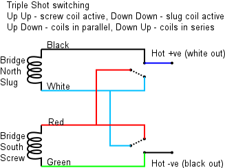
Series Parallel wiring using a rotary switch in place of a varitone.

RIDMIK

New member
Just bought two Pearly Gates for my 1968 es 345. Basically, after all these years, I'd like to remove the chokes and varitone and I'm replacing the pick ups as well which are pretty shot. In place of the varitone switch, I'd like to place a rotary switch. I was hoping to just use two positions. Pos 1 would be both humbuckers selected for series wiring. Pos. 2 would be both humbuckers selected for parallel. I want to keep it simple and think this option would be cool. Post the switch I want to keep the 3 pos. toggle switch. I ordered a pre wired ES 335 harness. I also found a 4 pole switch, 6 pos. from Stew Mac and have that now. Is there way to move the rotary switch to pos 2 and have the pickups change from series to parallel?
Thanks for your help.
 
Re: Series Parallel wiring using a rotary switch in place of a varitone.

Easy enough if you approach this systematically. Here is a schematic of the triple-shot switching that does what you want.

1-TripleShotSwitching.png

You need to transfer this to a 4-pole 6-position switch.

Attach the White from the pup to the pole 1 common lug and the Red to the pole 2 common lug.
Attach the Red to the pole 1 position 1 lug and the white to the pole 2 position 1 lug.
Only one of these two is really needed.

Attach the Green to the pole 1 position 2 lug and then to ground.
Attach the Black to the pole 2 position 2 lug and then to the volume pot input lug.

Repeat with the other pickup and poles 3 and 4.

Done.

As the pole common lugs are connected to White and Red, you could use 4 more of the positions for selecting single coils in pairs: front, back, inside or outside pair.
 
Last edited:
Re: Series Parallel wiring using a rotary switch in place of a varitone.

Thanks very much. So it seems with the rotary switch, I'm limited to choosing one pick up to have the options of the triple shot switch which makes sense as that switch applies to a single pick up on the ring. I think I'd choose the neck pickup.
 
Re: Series Parallel wiring using a rotary switch in place of a varitone.

You only need a 4PDT switch to do what you want. You wire it the same as a DPDT switch for one pickup, except that there are two identical sections.
 
Re: Series Parallel wiring using a rotary switch in place of a varitone.

You only need a 4PDT switch to do what you want. You wire it the same as a DPDT switch for one pickup, except that there are two identical sections.

Yup. Fender' S-1 push/push pot is a good candidate for this (but expensive as hell).
Any other toggle 4PDT on/on switch will work.
 
Re: Series Parallel wiring using a rotary switch in place of a varitone.

Thanks very much. So it seems with the rotary switch, I'm limited to choosing one pick up to have the options of the triple shot switch which makes sense as that switch applies to a single pick up on the ring. I think I'd choose the neck pickup.

I say "Repeat with the other pickup and poles 3 and 4." This means that both pickups get the extended triple shot selection. Both pickups with serial coils, both pickups with parallel coils, and any of the 4 combinations of 2 single coils with the selector switch in the middle position. Having all 4 single coil options is a bit of overkill but you have your eye on a 6 way switch which makes it possible.

As ArtieToo says, if you don't want or need the single coil options you can do it with just a 4PDT on/on switch.
 
Last edited:
Re: Series Parallel wiring using a rotary switch in place of a varitone.

If you want a rotary, you need one with 4 poles (2 wafers, usually).
But, I don't know of a rotary adequate to guitar with just 2 throws.
Minimum I've seen for a rotary is 3 throws.
But, there are rotaries with stoppers, so you can use a 6 throws with just 2 of the positions. Position 3 and beyond is stopped!.
 
Re: Series Parallel wiring using a rotary switch in place of a varitone.

So, with the 4 poles, each turn of the switch effects all 4 poles? If that's the case, it's exactly what I'm looking for and have the tech wire the pickups as such. Of course, I'd want the less needed options further on in the switch positions. It's easy to throw a switch from 1 to 2 or 1 to 3. Not so easy to hit the other positions on the fly. I'm hoping to fit the switch into the 345 via the neck pick up cavity. It definitely won't make it through the F Hole. Sorry to be so dense about the electronics. It's just not my expertise at all. Thanks for the input.
 
Re: Series Parallel wiring using a rotary switch in place of a varitone.

So, with the 4 poles, each turn of the switch effects all 4 poles?

Yes, each click of the switch affects all 4 poles at once.

If that's the case, it's exactly what I'm looking for and have the tech wire the pickups as such.

If you or your tech can't figure out from the diagram which wires should be connected to which lug, I can list them on request.
 
Re: Series Parallel wiring using a rotary switch in place of a varitone.

If it's not too much trouble, I'd sure appreciate the help. This way I go straight to him with all the parts, etc and hope it all works out.
 
Re: Series Parallel wiring using a rotary switch in place of a varitone.

Please excuse the detailed explanation. It's so I can keep it all clear in my head as I write.

I don't know what order you want the combinations so I am going to letter the positions A through F. You need to assign a number to each position in the order you want them and solder accordingly.

Wires attached to the pole 1 and 2 common and position lugs come only from the neck pickup.
Wires attached to the pole 3 and 4 common and position lugs come only from the bridge pickup.

Each pickup wire colour is connected to more than 1 lug. Connect the wire from the pickup to one lug then connect to the other lugs of the same wire colour with insulated jumper wires.

[TABLE="class: grid, width: 650"]
[TR]
[TD][/TD]
[TD]Neck[/TD]
[TD]Bridge[/TD]
[TD]Position[/TD]
[TD]Neck[/TD]
[TD]Neck[/TD]
[TD]Bridge[/TD]
[TD]Bridge[/TD]
[/TR]
[TR]
[TD]Order (1-6)[/TD]
[TD]Coil[/TD]
[TD]Coil[/TD]
[TD](Lug)[/TD]
[TD]Pole 1[/TD]
[TD]Pole 2[/TD]
[TD]Pole 3[/TD]
[TD]Pole 4[/TD]
[/TR]
[TR]
[TD][/TD]
[TD][/TD]
[TD][/TD]
[TD]Common[/TD]
[TD]Red[/TD]
[TD]White[/TD]
[TD]Red[/TD]
[TD]White[/TD]
[/TR]
[TR]
[TD][/TD]
[TD]Series[/TD]
[TD]Series[/TD]
[TD]A[/TD]
[TD]White[/TD]
[TD]Red[/TD]
[TD]White[/TD]
[TD]Red[/TD]
[/TR]
[TR]
[TD][/TD]
[TD]Parallel[/TD]
[TD]Parallel[/TD]
[TD]B[/TD]
[TD]Black[/TD]
[TD]Green[/TD]
[TD]Black[/TD]
[TD]Green[/TD]
[/TR]
[TR]
[TD][/TD]
[TD]Screw[/TD]
[TD]Slug[/TD]
[TD]C[/TD]
[TD]Black[/TD]
[TD]Red[/TD]
[TD]White[/TD]
[TD]Green[/TD]
[/TR]
[TR]
[TD][/TD]
[TD]Slug[/TD]
[TD]Screw[/TD]
[TD]D[/TD]
[TD]White[/TD]
[TD]Green[/TD]
[TD]Black[/TD]
[TD]Red[/TD]
[/TR]
[TR]
[TD][/TD]
[TD]Screw[/TD]
[TD]Screw[/TD]
[TD]E[/TD]
[TD]Black[/TD]
[TD]Red[/TD]
[TD]Black[/TD]
[TD]Red[/TD]
[/TR]
[TR]
[TD][/TD]
[TD]Slug[/TD]
[TD]Slug[/TD]
[TD]F[/TD]
[TD]White[/TD]
[TD]Green[/TD]
[TD]White[/TD]
[TD]Green[/TD]
[/TR]
[/TABLE]

In addition:
Connect the Green wires from both pickups to ground (along with everything else that does not carry a signal).
Connect the Black wire from the neck pickup to the input lug of the neck volume pot.
Connect the Black wire from the bridge pickup to the input lug of the bridge volume pot.

With the selector switch in the middle position, positions A, B, C and D are all humbucking modes, E and F are not.

I think that should do it.
 
Re: Series Parallel wiring using a rotary switch in place of a varitone.

Thank you. I copied all this and dropped it off with my guitar. First snafu was that the length of wire off the neck pick up was not sufficient to reach the switch or for that matter it was not going to reach the pots either. You'd think they would have added enough wire to accommodate a 345/335 which is a common instrument. Again, it was very kind of you to take the time to map this out for me.
 
Back
Top