Seymour Duncan Liberator/Install woes

crsnhppr

New member
Click image for larger version  Name:	6AB0FDCB-3A5A-41CD-A17C-6B7AC4A0F9C9.jpg Views:	5 Size:	16.1 KB ID:	6195858 Click image for larger version  Name:	6AB0FDCB-3A5A-41CD-A17C-6B7AC4A0F9C9.jpg Views:	5 Size:	16.1 KB ID:	6195858So….

Intended set is this:
2 SD humbuckers
1 CTS push pull 500l pot (the one with the little circuit board)
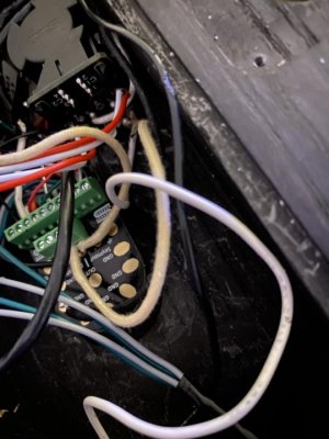
3 way blade,
liberator.

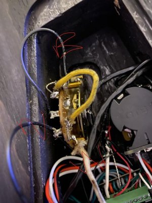
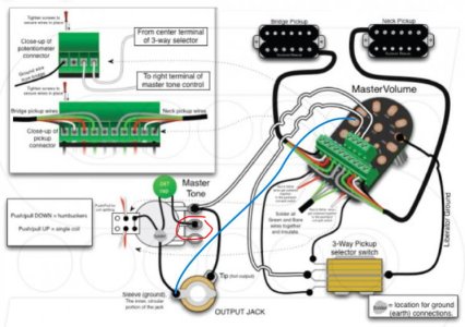
I’ll include images of the wiring diagrams I attempted to follow. I can’t understand the wiring the way the 3 way blade is suppose to go because the SD diagram for the liberator shows it using a “switch”. I looked up the closest thing I could find and watched some YouTube videos about oak grisby 3 way blades and found a couple images online on how to wire them.

ive spent probably 8 hours trying to wire this thing up correctly over the past 2 days and before I take it to the luthier Monday maybe someone can help me.

when i wired it up the first time basically copying the liberator diagram scheme provided I used the wiring for the 3 way blade from the “other” diagram and my middle pickup selection , position 2 would not engage. The coil taps worked and the bridge and Neck pickup worked as well but no middle anything.

i have just attempted 2 more wiring combinations and they didn’t work either , either it was both pups together all the time or a combination of the middle and neck or middle and bridge together. Also the tone knob (the cts push pull) just acts like a master volume..

so there we are. Can anyone show me with wiring diagrams for what I’m attempting or offer any help?

also on the liberator scheme diagram it said hook that wire coming from the liberator to the center of the 3 way switch , I tried guessing what the center was from another diagram of the oak grisby and that was obviously wrong as well. I also tried doing the wire from the liberator to look like the one in the diagram and that didn’t work right either. Then there’s another diagram similar but wires are going different places so idk what’s going on or how to do it.
 
Last edited:
The Duncan drawing has an error in it. It's showing the bridge hot going to where the common master volume (ilberator) would go, and vice-versa.
 
The Duncan drawing has an error in it. It's showing the bridge hot going to where the common master volume (ilberator) would go, and vice-versa.

So the black bridge wire goes to the master tone pot? What about the black neck pickup wire? And now where do those two white wires coming outta the liberator go now?

i got the 3 way “working”recently before I read what you said. I have not corrected the flaws from what you said are wrong in the diagram yet I just unjumped some switch leads and moved the white wire from the liberator where it says “from center terminal of switch” to the location in the 3 way blade diagram in the other diagram. I can select bridge , middle, and neck pickups and the coil splitting works. It’s just now my tone knob acts like a master volume. I don’t have a .047uf cap but I don’t think that would be the flaw in the circuit.

thanks for your help.
 
I had 2 clients try them, and did not like them. Didn't take long for either of them to remove the Liberator and tried different mods to get the sounds they wanted. I sold the ones I had left in stock for cost just to get rid of them. Not Seymour's finest product IMO.
 
The Liberator doesn't make any sounds (other than function as a volume or tone). It just allows swapping pickups without soldering. I've found it works great. I auditioned 10+ pickups in my Jackson with it.
 
So the black bridge wire goes to the master tone pot? What about the black neck pickup wire? And now where do those two white wires coming outta the liberator go now?

No. You would need to swap the Bridge Tone and Master Volume wires at the switch in the drawing.

If the Liberator is functioning as your master volume, then the white wire going to the switch in the liberator drawing is the same as the black one between the master volume and the switch (after swapping as I just stated), and the other white wire would go to the jack.
 
I like the Liberator. Especially if you have a 'test guitar' and want to swap pickups regularly.
 
The Liberator doesn't make any sounds (other than function as a volume or tone). It just allows swapping pickups without soldering. I've found it works great. I auditioned 10+ pickups in my Jackson with it.

”No. You would need to swap the Bridge Tone and Master Volume wires at the switch in the drawing.

If the Liberator is functioning as your master volume, then the white wire going to the switch in the liberator drawing is the same as the black one between the master volume and the switch (after swapping as I just stated), and the other white wire would go to the jack.”

I’m still not understanding what your saying. Right now both tone and master are working like master volumes. Are you saying I have to just move these wires at the switch and then take the other white wire coming out of the liberator and solder it direct to the Jack? Which part of the Jack? I labeled where the wires are now currently with both knobs working like volumes and the other picture shows where the other white wire goes to the push pull and there another white wire from the Jack going there.
 

Attachments

  • 38106112-F2DA-4A5E-9760-E29E557287AA.jpg
    38106112-F2DA-4A5E-9760-E29E557287AA.jpg
    60 KB · Views: 0
  • D3298451-BA63-4179-8F6B-66787A118984.jpg
    D3298451-BA63-4179-8F6B-66787A118984.jpg
    52.4 KB · Views: 0
BTW, in that diagram, they left off the "master" ground. There must be a wire soldered from any one of the Liberator solder pads, to the sleeve of the output jack. As it is now, only the tone control is grounded.
 
BTW, in that diagram, they left off the "master" ground. There must be a wire soldered from any one of the Liberator solder pads, to the sleeve of the output jack. As it is now, only the tone control is grounded.

That white wire coming off the liberator goes to the tone pot terminals that’s grounded. The liberator pad shows a black wire going to a ground on the switch. I didn’t see a “ground” place on the switch I got so I just took a wire and soldered a pad on the liberator connected to where that white wire and terminal link to the ground on the pot.

?

I mean it’s not humming or anything. But like I said, tone knob still acts like a volume and master volume (what I intended to be the master volume/liberator) acts like a volume too.
 
If the tone knob is acting like a volume, your tone cap is likely shorted out by the legs touching something they aren't supposed to, or the cap is not getting connected to ground properly.
 
That white wire coming off the liberator goes to the tone pot terminals that's grounded. The liberator pad shows a black wire going to a ground on the switch.

Sorry, but you're misreading the diagram. One white comes from the output of the 3-way and feeds to the input of the Liberator pot. The other white wire comes from the wiper (output) of the Liberator pot and feeds to the "hot" side, or input, of the tone pot. And while yes, the Liberator ground pad goes to the ground of the 3-way, it goes no where else after that. The whole right side of the diagram, (pups, Liberator, and 3-way), have NO connection to the sleeve of the output jack, which is the only true ground in the circuit.

There MUST be a ground wire soldered from the Liberator pad to the output jack sleeve, (ground lug), for this circuit to work.

Edit: The two terminals to the right of the white wires are both ground. They can also be run to the ground lug of the output jack if you don't want to solder to a Liberator pad.
 
Last edited:
Here's the corrected diagram, using a blue line to indicate the missing ground connection.


So if I just get that ground wire hooked up like you showed in the diagram it’ll all work correctly? I don’t have to change where my wires are at now on the switch? What about the white wire connected from the liberator to the tone pot terminal?
 
If the tone knob is acting like a volume, your tone cap is likely shorted out by the legs touching something they aren't supposed to, or the cap is not getting connected to ground properly.


i don’t have a capacitor on this pot but since I didn’t have one I just jumped this terminal to a ground on the pot. Should I remove that to alleviate it functioning as a volume?

i circled what I’m referring to in red. Do I just remove that connection?
 

Attachments

  • 8A869C42-B7ED-416B-BC49-94616F194B55.jpg
    8A869C42-B7ED-416B-BC49-94616F194B55.jpg
    89.6 KB · Views: 0
I’m giving up and taking somewhere sorry to waste y’all’s time. Thanks for the help.

I tried wiring it up again with a new pot and added the ground wire and it still was not working correctly.
 
Don't give up. I'm not at home right now. When I get on my main computer, I can answer this better for you. Patience.
 
Don't give up. I'm not at home right now. When I get on my main computer, I can answer this better for you. Patience.

I threw the liberator in the trash. I have 2x cts push pulls leftover , the ones with the pcb terminals,. Is there a correct diagram for that you can show me? Maybe I can get that to work.
 
I mean I’ll try again if you can help. This last time I wired it up, the bridge and neck pup worked, not the middle position. Then the tone knob wasn’t acting like a master but It wasn’t working at all either. And the coil splitting function worked on the bridge but took the neck out of circuit when pulled up. So it got worse basically. I still have 1 in molested cts push pull but I’ll try using the one I just wired up again I guess. Idk. Frustrating as hell trying save a buck doing it yourself then you just end up paying more because you’ll be sending it off anyway.

I got the liberator out of the trash and will try to idk. Do it again I guess.
 
Last edited:
Back
Top