Recently purchased a Sterling AL40 Albert Lee. Got it used for a good price. The bridge humbucker sounds thin and weak. Checked SD wiring diagram for 2 HB, 1 vol, 1 tone, 5-way superswitch. While I understand that the color codes may not match, I can still see that the way this guitar is wired is not like the SD diagram. I also noticed one of the jumper wires is disconnected on one end. Rather than unsolder everything and start over, I was hoping to find a wiring diagram of the guitar to see if it's something simple rather than start over. While I have some experience with wiring and soldering, I'm no guitar electronics expert. Thanks in advance.
You are using an out of date browser. It may not display this or other websites correctly.
You should upgrade or use an alternative browser.
You should upgrade or use an alternative browser.
Sterling Albert Lee Wiring Diagram
- Thread starter MikeWiles
- Start date
beaubrummels
Well-known member
I thought Mincer did a wiring for this scheme in a blog article?

Edit: I think this might be the 'official' one

looks like it's the same as the Axis

Edit: I think this might be the 'official' one
looks like it's the same as the Axis
Last edited:
Yes, I wired my Silhouette Special like this. But first we have to find out if the Albert Lee's 2 humbuckers are wired the same way, and if they accomplish that with a Super Switch. My wiring depended on the neck humbucker having its magnet flipped, too. I don't know if the Sterlings have a proprietary switch.
I compared the diagram you provided with the Sterling AL40 as I received it and is currently how it is. I revised it to show what I currently have. I don't yet understand how a superswitch works. So if someone sees what will correct the issue, I'm open to suggestions. Thanks again.
Attachments
I plan to rewire this weekend according to the MusicMan diagram posted. Not sure if the color codes are the same as Sterling or not. At this point, I will assume they are the same. Hopefully, this will correct the issue. If not, hopefully it is just flipping the magnet over. Thanks for the advise guys!
Jack_TriPpEr
Well-known member
I plan to rewire this weekend according to the MusicMan diagram posted. Not sure if the color codes are the same as Sterling or not. At this point, I will assume they are the same. Hopefully, this will correct the issue. If not, hopefully it is just flipping the magnet over. Thanks for the advise guys!
Wiring color codes and whether either pickup you have in hand has reversed polarity and reversed wind (RWRP), or just reversed polarity (magnet flipped), or neither, is a big deal for knowing how to get this wiring scheme to work correctly. ArtieToo and I just went through some hoops helping Mincer troubleshoot a recent similar wiring scheme.
The key to avoiding headaches and mysterious problems, is to use a multimeter and a compass to take some key measurements for the two pickups you have in hand, before you even turn on the soldering iron.
Here's a video that shows you how to use the compass and multimeter to take those key measurements for each pickup:
I will unsolder the pickups and test them before doing anything else. Now that I've made the wiring diagram, I can always get back to the original wiring. Thanks for the advise. If I were to guess, it's probably the red and green wires swapped on the bridge pickup connections. They look reversed.

Jack_TriPpEr
Well-known member
I unsoldered the pickups from the guitar. I used a multimeter to determine coil pairs and polarity. Here's what I found: Not sure how this relates to the diagram as I don't know the details on the pickups shown above. Thanks for any help.
One key metric I don't see mentioned abovein what you tested for: the magnetic polarity of each coil. Did you do the compass test to find that out?
Besides that, based on what you did report, it seems that one pickup has a different magnetic orientation than the other one, since the same colored wires on each pickup have different electrical polarities ( i.e. green on one is + but green on the other -). That suggests that one of your pickups is reversed polarity (RP) only, vs Reverse Wound (RW) and RP. That's a big help in figuring out any wiring color code translations needed to make these pickups work with that Music Man diagram.
I'll do a little internet research about your plus put some time into studying the Music Man diagram and give you some feedback later tonight or in the morning.

Jack_TriPpEr
Well-known member
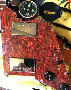
I purchased a compass this morning. Here are the results:
Hmmm.. if those compass measurements are correct, that would mean - if using the original Music Man diagram - the coils being combined in Positions 2 and 4 would not be hum-canceling. I.e. the two outer coils in Position 4 both being North magnetic polarity, and the two inner coils in Position 2 both being South magnetic polarity. To be hum-canceling, the two coils being combined need to be opposiite magnetic polarity of each other. But this type of diagram is known for being designed so that Positions 2 and 4 are hum-canceling. So something is off.
I would advise you double-check the magnet test. Did you catch how the guy in the instructional video said that the end of the needle marked North is actually a South magnet?
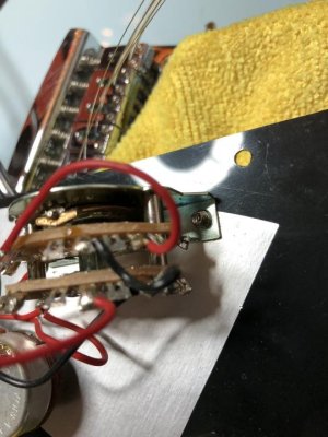
The other thing that would help at this point, is some photos of the current switch and wires attached to it. Also, the undersides of each of the two pickups, to verify that the two pickups are original to the guitar or not. And if not, to be able to ID what those pickups are.
I happen to be on vacation right now so unfortunately my availability to check back in is going to be limited over the next couple days. Hopefully some of the other forum members can help out.
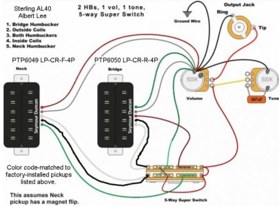
I made a mistake in the last diagram. After gather some photos to post, I realized that I had the bridge pu 'north' marker on the wrong coil. Here's a correct diagram. Sorry for the confusion. 
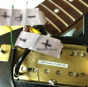
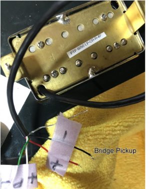
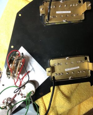
Here's some pics of the layout, backside, and pickups. There is a label on the neck pickup: PTP6049 LP-CR-F-4P. There is an 'F' steel stamped into the brass backplate. The label on the bridge pickup is: PTP 6050 LP-CR-R-4P. It also has an 'F' steel stamped on the brass backplate. Here's some pics:
Here's some pics of the layout, backside, and pickups. There is a label on the neck pickup: PTP6049 LP-CR-F-4P. There is an 'F' steel stamped into the brass backplate. The label on the bridge pickup is: PTP 6050 LP-CR-R-4P. It also has an 'F' steel stamped on the brass backplate. Here's some pics:
Attachments
Jack_TriPpEr
Well-known member
I made a mistake in the last diagram. After gather some photos to post, I realized that I had the bridge pu 'north' marker on the wrong coil. Here's a correct diagram. Sorry for the confusion.
Here's some pics of the layout, backside, and pickups. There is a label on the neck pickup: PTP6049 LP-CR-F-4P. There is an 'F' steel stamped into the brass backplate. The label on the bridge pickup is: PTP 6050 LP-CR-R-4P. It also has an 'F' steel stamped on the brass backplate. Here's some pics:
Thanks for the updated info and the pics.
The latest info you provided about the magnet orientation, aligns to what I know would work for hum-canceling in Positions 2 and 4.
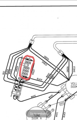
The Music Man diagram not only depicts the lower set of poles in a weird physical orientation that I've never seen on an actual 5 way superswitch (see the two poles I have circled in Red in the attached pic), ...
but we can also see from your pics, that your 5 way superswitch does not have that orientation. Your switch looks like common 5 way superswitches that I am familiar with.
Also, the way that those 2 particular poles are wired in the Music Man diagram, makes no sense to me and I don't see how it could work wired that way. So for these multiple reasons, my advice is to abandon that Music Man diagram.
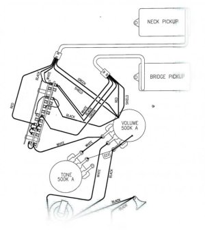
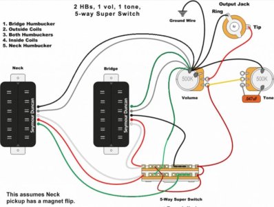
And instead, use the following diagram, but with the following wire color substitutions:
Neck Pickup:
Green in digram: use your green wire (no change)
Red & White in diagram: use your Black & White wires
Black in diagram: use your Red wire
Bridge pickup:
Black in diagram: use your Red wire
Red & White in diagram: use your Black & White wires
Green in diagram: use your Green wire (no change)
This replacement diagram is the outcome from the recent troubleshooting ArtieToo and I did for Mincer's diagram where he was looking to get the same 5 positions that you want. (Ref: Reply #76 in this other thread: https://forum.seymourduncan.com/for...out-my-do-it-all-wiring?p=6088171#post6088171
)
Let me know how it works out after you get it wired up!
Attachments
Jack_TriPpEr
Well-known member
Another wiring color substitution:
The red wire in the diagram coming fron the 5 way switch to the volume pot = use the white wire you have coming off your volume pot. This assumes that the connection btw your volume pot and the 5 way switch closely matches the Music Man diagram.
And assuming the wiring of your volume pot and tone pots closely matches the Music Man diagram and they seemed to be working without issue, you do NOT need to rewire your tone or volume pots to match the replacement diagram i just provided.
The purpose of the placement diagram is specifically for conect the wires fron each pickup to the 5 way switch. The rest of your existing wiring should be fine. However, you should also be fine if you did want to rewire your volume pot and tone pot to match the replacement diagram, but it should not be necessary.
Another wiring color substitution:
The red wire in the diagram coming fron the 5 way switch to the volume pot = use the white wire you have coming off your volume pot. This assumes that the connection btw your volume pot and the 5 way switch closely matches the Music Man diagram.
And assuming the wiring of your volume pot and tone pots closely matches the Music Man diagram and they seemed to be working without issue, you do NOT need to rewire your tone or volume pots to match the replacement diagram i just provided.
The purpose of the placement diagram is specifically for conect the wires fron each pickup to the 5 way switch. The rest of your existing wiring should be fine. However, you should also be fine if you did want to rewire your volume pot and tone pot to match the replacement diagram, but it should not be necessary.
Thank you so much for the help Jack. I wired the pickups and the switch jumpers according your diagram and making the color substitution. It all works as it should now.
I marked up your drawing to include the color code change. I added info on the guitar model and the pickup numbers. I thought I'd post it here in case this helps someone else in the future. I greatly appreciate everyone's effort to help this old noob. Now, the guitar sounds as good as it plays and looks!

Attachments
Jack_TriPpEr
Well-known member
Thank you so much for the help Jack. I wired the pickups and the switch jumpers according your diagram and making the color substitution. It all works as it should now.
I marked up your drawing to include the color code change. I added info on the guitar model and the pickup numbers. I thought I'd post it here in case this helps someone else in the future. I greatly appreciate everyone's effort to help this old noob. Now, the guitar sounds as good as it plays and looks!
Great to hear, Mike!
Thanks for keeping "the next guy" in mind! Very admirable! Thanks for contributing to the community here!
Similar threads
- Replies
- 3
- Views
- 341
- Replies
- 6
- Views
- 1K
- Replies
- 1
- Views
- 220
- Replies
- 1
- Views
- 147