Tele Hot Rails wiring help / 4 way switch / 2 push pull pots coil split
Hi Dwh0... and welcome to the forum!
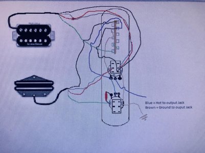
It looks to me like you have it almost figured out... that diagram should work pretty good!
That being said, since you said you're having trouble understanding why the neck green is connected to the 4-way and how the switch works, I'll try to make it a little more clear for you. As it is, they have everything to do with one another, so let's see if we can make it make sense.
First of all, your 4-way switch connections work like this:

Each side (pole) of the switch works separately from the other. Each one also has a "common" which is denoted by A0 and B0 on the diagram. The other A's and B's are numbered as the switch positions (1-4). The common is ALWAYS connected to one (and ONLY one) of the other terminals depending on what position the switch is in.
As for the green wire from the neck vs the green from the bridge, the green returns to ground along with the bare ground wire in most instances. If the black is the "hot" or "+", then the green is the "-" of the pickup. Think of it as the signal from the amp coming into the "+," through the pickup, and going out the "-" (that's not actually technically correct, since the pickup actually creates the signal, not your amp... but that's another discussion; for now this will work).
So lets look at what each of the switch positions does:
#1) The hot comes from the jack, through the volume and into the B1 terminal on the switch, which connects to the common (B0). The black "hot" wire from the bridge pickup is attached to common, so the connection continues through the north coil coming out on the white wire, which is connected to the red... the end of the south coil. The green is the start of the south coil, so the connection then continues to ground.
- Note: If you have the Tone push/pull in the "up" position, the ground connects to the red & white, bypassing the south coil altogether. Your neck pickup does the same thing using the push/pull on the Volume control.
- Notice that the hot wire for the neck pickup is permanently attached to the hot coming off the volume control... yet the pickup isn't on in position #1. If you follow it through the pickup you'll see that the green comes back to the A0 common which connects to... nothing! Since there isn't anything on the A1 terminal, the signal never makes it back to ground and the pickup remains silent.
#2) Here the hot from the volume is physically connected via a jumper to B2 as well, so the bridge pickup functions exactly as it did in position #1. The difference is that this time the green from the neck pickup connects to A2, which is connected to A3 and ground. The signal is able to make it all the way through the neck pickup and back to ground this time, so you have BOTH pickups going. Since they take a single signal (from the volume) and split into the two pickups running simultaneously we call it running the pickups in parallel with one another.
#3) In position #3 you can see that there is nothing connected to the B3 terminal, therefore no hot signal is sent to the bridge pickup and it remains silent. The neck pickup operates just as it did in position #2.
#4) This is the tricky one, and also the one that shows you why the green from the neck MUST be connected to the switch instead of straight to ground like the bridge pickup. So the hot comes from the volume control to B2 on the switch, which is not connected to common and therefore doesn't push on into the bridge pup. It goes into the black on the neck pickup and comes out the green, back to the switch. Then, since the switch is in position #4, it connects to A4 and a jumper wire sends it over to B4 which IS connected to common and the signal now passes through the bridge pickup and finally to ground. So now you have a single signal going through the neck pickup and THEN the bridge pickup. We call this connection "in series."
So that's how it works, now for a suggestion...
You should reverse the split on the neck pickup so that it's running the south coil instead of the north coil. Let's say you had the neck split and wanted to switch to position 4 where the pickups are in series with one another. The hot would go in the black and out the white and... to ground. The signal doesn't get to make it to the red wire and the green... therefore never making it to the bridge pickup. You'd have the same thing as position #3. Instead, you want the hot, when split, to go to the red wire so that it can continue on. This setup also gives the added advantage of hum-canceling when running both pickups split. Try doing it like this instead:
I hope that helps get you going. Be sure to come back and tell us how it all comes out! :fing2:


 .
.