Re: Troubleshooting no sound (short?) on new build?
EDIT: well, looks like it may be the jack itself. Strange, because it worked fine before. If I don't push the cable in all the way, all the electronics work as expected. Maybe I melted something in the jack when I resoldered... Thank you guys for all the help!
Edit 2: I think I figured out what happened... It looks like the Jack is stereo/mono and I must have soldered both the top pins together, shorting it out when a lead was plugged in. Knucklehead mistake for sure.
Thank you - I think I know what you mean about the bare ground wires, but my pickups don't have that style. The only differences I have from the wiring diagram is that my guitar already had grounds from the pickup cavities to the control cavity. I wired those up and grounded to one of the common grounds on the pot body.
I've tried to get a few pics - bit hard to see so I've tried to caption each one:
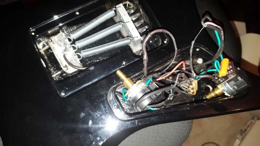
pic 1: full control cavity, volume pot on left, tone on right.
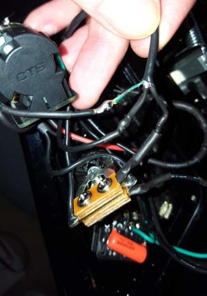
pic 2: 3 way toggle switch - black wire from neck pickup on either outside terminal, left-most tab of volume pot (when viewed from the back) to center terminal, ground on body of vol pot to single terminal on the other end of the switch.
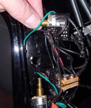
pic 3: volume pot - green and bare wires from neck pickup soldered to pot body, red and white wires from neck pickup soldered to C1 on push/pull switch, body of pot joined via wire to position 2 on the push/pull switch, trem claw ground and 2x pickup cavity found wires soldered to body of pot, control cavity ground wire soldered to body of pot. Body of pot (ground) connected to body of tone pot via wire. center tab of pot soldered to hot/center tip of output jack (red wire), leftmost tab of volume pot (viewed from behind) connected to center position of toggle switch and to right-most tab of tone pot (viewed from behind with tabs facing down).
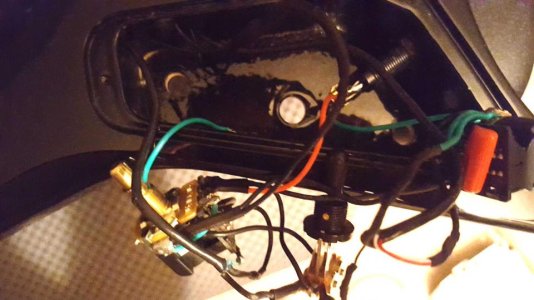
pic 4: everything pulled out of cavity
pic 5: tone pot - capacitor legs shrink wrapped to avoid shorts, capacitor leg connected to center tab and other leg connected to body of pot. (don't know if these capacitors go in a right and a wrong way?). green/bare wires of bridge pickup soldered to body of pot, bridging wire from body to position 4 on push/pull switch. red & white wires from bridge pickup soldered to position c2 on push/pull switch. tone pot body grounded to sleeve of output jack (green wire). left-most tab of tone pot removed for clearance.
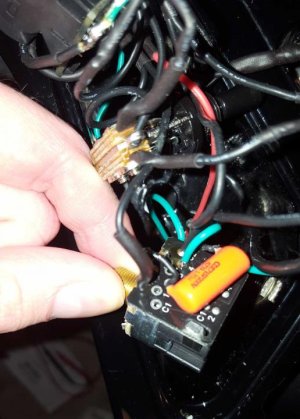
pic 6: tone pot grounds on side of housing.
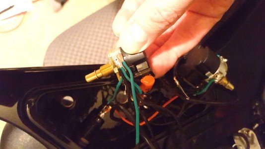
This is the diagram I followed:
https://docs.google.com/gview?embed...t/uploads/2016/05/2H_3G_1VppSPLn_1TppSPLb.pdf and the only differences mine has is that the pickup cavities and control cavities are also connected to the same ground as the trem claw. These extra 3 grounds simply screw into the wood body of the guitar.
Realize these pictures are dark and the wiring is beautifully neat, but if anyone has any suggestions I'd massively appreciate it. I didn't test the pickups prior to installing - they were brand new. Happy to clarify any wiring questions etc.
thank you!


