You are using an out of date browser. It may not display this or other websites correctly.
You should upgrade or use an alternative browser.
You should upgrade or use an alternative browser.
What does this wiring do?
- Thread starter orpheo
- Start date
beaubrummels
Well-known member
Looks to me like
1. Bridge
2. Bridge slug coil
3. Bridge + Neck
4. Bridge + Neck in series
5. Neck
1. Bridge
2. Bridge slug coil
3. Bridge + Neck
4. Bridge + Neck in series
5. Neck
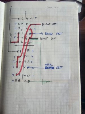
I'm reading this differently. It's confusing. It's not a normal Super Switch layout. Usually the wafers are identical side by side. The 2 outermost lugs on either end are common. This is laid out like a pinwheel with one side 0-5 and the other 5-0. Between this and 3 leads only I first thought it was a variation of a PRS rotary drawing but I don't think so now.
I'm reading this as if the pickups are Duncan standard 4 color wiring. Hots would be Black, Splits are Red+White tied together, and Green is Ground. The Neck ground isn't shown so assume its permanently grounded to the back of the volume pot.
That makes 1,3,5 the expected sounds. 1- Bridge HB, 3- Bridge HB & Neck HB, 5 Neck HB.
P2 and P4 I checked several times because the layout makes it easy to mix lugs up.
In P2 the bridge Hot is connected to the output and the Split (series join) shorts to ground. Therefore the Neck Split connection to lug V isn't actually doing anything. This will give Bridge inner coil only. If the goal was to have both coils split to inner coils in P2, that can be done by extending the Neck hot jumper from lugs G-I on to lug J.
In P4 the full Neck HB is connected to output normally. The Bridge Ground is connected to output and the Bridge Hot is connected to Ground. This will be Neck HB & Bridge HB in Parallel Out Of Phase. This will sound very weak. It isn't very usable on a guitar with a single master volume. There's a few ways to include caps and/or resistors to get a more usable half out of phase sound.
As its now drawn I see...
1- Bridge HB
2 - Bridge Inner Coil
3 - Bridge HB & Neck HB
4 - Neck HB & Bridge HB in Parallel out of phase
5 - Neck HB
X, R, F, and L are common per pole of this 4pole 5way switch. I would have guessed that in position 2, because X is also connected to ground, the neck is split as well.
I think this should be:
1: bridge
2: bridge and neck split, in series
3: bridge and neck parallel
4: bridge and neck series out of phase
5: neck
Is that what this is?
I think this should be:
1: bridge
2: bridge and neck split, in series
3: bridge and neck parallel
4: bridge and neck series out of phase
5: neck
Is that what this is?
Here's a simplified version of the connections in P2. The neck pickup has 3 leads connected to ground but none to output. A short jumper from Lug I to J will connect the neck black lead to output in P2. This will bring the neck inner coil into the circuit in parallel with the bridge inner coil.

This is VERY crude, but it was faster to photo-edit to show what I meant because the switch layout doesn't match my templates. Left side is cleaned up a little with Duncan color codes overlaid. Right side traces the output to ground paths in P4. Blue is Neck, Orange is Bridge. The outlined segments are the internal switch connections. It is what I said earlier Bridge and Neck full humbuckers out of phase in parallel.

If you want these 5 positions with 2 and 4 series connections I have an almost identical scheme on a regular super switch layout.. It just has 2,3,4 in a different order. I can post an updated one here if you want....let me know
1: bridge
2: bridge and neck split, in series
3: bridge and neck parallel
4: bridge and neck series out of phase
5: neck
Teleplayer
Active member
Pos 1: bridge
pos 2: bridge (slug coil only)
Pos 3: neck and bridge (in phase)
Pos 4: neck and bridge (out of phase)
Pos 5: neck
I don’t think the neck pickup is selected in pos 2. Do you have a pic of the installed wiring?
pos 2: bridge (slug coil only)
Pos 3: neck and bridge (in phase)
Pos 4: neck and bridge (out of phase)
Pos 5: neck
I don’t think the neck pickup is selected in pos 2. Do you have a pic of the installed wiring?
Pos 1: bridge
pos 2: bridge (slug coil only)
Pos 3: neck and bridge (in phase)
Pos 4: neck and bridge (out of phase)
Pos 5: neck
I don’t think the neck pickup is selected in pos 2. Do you have a pic of the installed wiring?
I have not wired my posted design ever.i found it in a notebook and I had no idea what it does. Clearly, it doesn't do what I want.
This is VERY crude, but it was faster to photo-edit to show what I meant because the switch layout doesn't match my templates. Left side is cleaned up a little with Duncan color codes overlaid. Right side traces the output to ground paths in P4. Blue is Neck, Orange is Bridge. The outlined segments are the internal switch connections. It is what I said earlier Bridge and Neck full humbuckers out of phase in parallel.
If you want these 5 positions with 2 and 4 series connections I have an almost identical scheme on a regular super switch layout.. It just has 2,3,4 in a different order. I can post an updated one here if you want....let me know
1: bridge
2: bridge and neck split, in series
3: bridge and neck parallel
4: bridge and neck series out of phase
5: neck
To have the 5 positions you mention would be great. 2 humbuckers in series without splitting them is useless.
The switch I have is the schaller M switch. L, F, X, R, are the common lugs for each pole of this 5 way switch.
To have the 5 positions you mention would be great. 2 humbuckers in series without splitting them is useless.
The switch I have is the schaller M switch. L, F, X, R, are the common lugs for each pole of this 5 way switch.
Oh I got it now. I forget Schaller has the customizable M switch not only the internally pre-wired versions. I can draw this up and post later today.
Here you go..let me know any questions. I use symbols and shorthand for some terms to help fit on a printed page at a larger size.
I don't know what pickups you will use. This assumes conventional Duncan PAF types So...this requires the Neck pickup magnet to be flipped 180 to make its inner (slug) coil South. This allows P2 inner (split) coils in series to be in phase hum canceling.
Photos I found of the switch indicate it would be installed with the A to M side face outward toward the guitar edge, the same as your pen drawing. So I've oriented it that way. If that's incorrect, let me know I'll fix it.
I remember why I only used the variant of this scheme only once. It's a pain to wire. It requires a lot of short jumpers close together in tight space. I try to consider physical layout on these schemes so no terminal has more than 2 connections to solder. On a Super Switch there are open lugs thin wire can be looped through to help. I think this will be even trickier on the single wafer solder pad design of the Megaswitch. YMMV... good luck.
sdugf-orpheo-s50.pdf
Last edited:
Here you go..let me know any questions. I use symbols and shorthand for some terms to help fit on a printed page at a larger size.
I don't know what pickups you will use. This assumes conventional Duncan PAF types So...this requires the Neck pickup magnet to be flipped 180 to make its inner (slug) coil South. This allows P2 inner (split) coils in series to be in phase hum canceling.
Photos I found of the switch indicate it would be installed with the A to M side face outward toward the guitar edge, the same as your pen drawing. So I've oriented it that way. If that's incorrect, let me know I'll fix it.
I remember why I only used the variant of this scheme only once. It's a pain to wire. It requires a lot of short jumpers close together in tight space. I try to consider physical layout on these schemes so no terminal has more than 2 connections to solder. On a Super Switch there are open lugs thin wire can be looped through to help. I think this will be even trickier on the single wafer solder pad design of the Megaswitch. YMMV... good luck.
sdugf-orpheo-s50.pdf
filedata/fetch?id=6318657&d=1754265466
This schematic looks great, thanks. I have no issue wiring the Schaller M-switch, done it many times before.
I am not happy with the inner coil setting, I always go for outer. Is that possible? The orientation seems fine to me. very thorough, I have to admit! Thanks!
Sure it can be outer coils. I'll get back to you on that. It should only need rearranging the pickups leads with switch jumpers unchanged.
The Duncan norm is split to inner coil because on a PAF type its slightly more output than screw coil, all else being equal.
I've always done inner coils in series because as I think someone here said its more like a "virtual" middle pickup especially on a 24 fret guitar. PRS and MusicMan John Petrucci used it. I'll have to try outer coils series I never have..
Artie
Peaveyologist
I've always done inner coils in series because as I think someone here said its more like a "virtual" middle pickup especially on a 24 fret guitar.
That was me. Also, while it's a bit more trouble, doing a mag flip, then "reverse wiring", allows inner or outer to remain humbucking.
The only place I remember seeing Outer Coils in Series is this diagram guitar electronics published over 20 years ago. It's odd they say its the PRS Rotary sounds from that time - this was before PRS moved to blades. I had access to the PRS line and service diagrams then. It was Inner Coils in Series 100%. PRS wiring has a lot more variants now that I'm not up to speed on.
I've only ever done Inner Coils in series on Vintage to mildly hotter PAF types under 9K. With clean to overdrive its a little crisper than both humbuckers in parallel the middle position, but still softer treble than if you had an actual series humbucker in the middle position.
There's plenty of threads here about Inner vs Outer splits and parallel combos and comments from Triple Shot users. The biggest thing is splitting the bridge HB to the outer coil can be weak and thin because its so close to the bridge itself.
Well here's the outer coil version. Enjoy!
Similar threads
- Replies
- 14
- Views
- 238
- Replies
- 3
- Views
- 408
- Replies
- 9
- Views
- 351
- Replies
- 9
- Views
- 658