Wiring Diagram Help for HH Strat

Frogman

New member
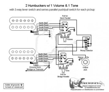
I can’t seem to find a SD diagram for my strat.


2 HB (JB / Jazz)
1 volume (push/pull): Jazz series/parallel
1 tone (push/pull): JB series/parallel
3 way blade


I figured I should do parallel instead of coil split since I play live all the time.


A SD diagram of the above would be most helpful!
Thanks in advance!
 
I don't know of a diagram that does what you want via push-pulls. The closest doagrams have the In Parallel options as Positions 2 and 4 on a five-way superswitch.

However, all you need to do is use the SD Wiring Diagram webpage and expand the category for "Miscelanous". There you should find a diagram for how to wire a push-pull pot to do Parallel or Series for a single humbucker. You will just combine that diagram with another diagram (also in the SD Wiring Diagram webpage) for 2 humbuckers and a 3 way blade selector.

Sent from my SM-G960U using Tapatalk
 
Do the main wiring like this, except (see below)...

2H_3G_1VppSPLn_1TppSPLb.jpg

...except do the pickups to the push pulls like this, and send the hot/black connector from the push pull to the switch instead of the volume lug:

1H_1VppSP.jpg
 
Use this diagram to wire each pickup for series/parallel, then wire the hot outs (the white coming off the bottom left lug) to a Tele 3-way switch. You'll get:

P1 - Bridge humbucker series or parallel
P2 - bridge and neck pickups in parallel with eachother, but the individual pickups either series or parallel
P3 - neck humbucker series or parallel.

You'll have two master volumes and you can couple the tone across the switch output for a single master tone.

WD1H10_04_WB__73323.1487884459.jpg - Click image for larger version  Name:	WD1H10_04_WB__73323.1487884459.jpg Views:	0 Size:	60.2 KB ID:	6109570
 
Last edited:
Note for independent volumes you may need to flip the black and white connections - hot in and hot out but leave the third lug grounded to the casing.

If you do, do NOT put pot casing grounds between the volume pots and the tone pot.

One other point, you could put a third push-pull on the tone and use that to coil split both pickups at once. You will have to decide which coil you want on which pickup, but the easiest way would be to route either the red or the white wire from each pickup to the central lug on the third push-pull with a wire back to the series/parallel push pull for that pickup from another lug. It'll be a straightforward on/off, so you may end up with an "everything off" if the series/parallel push pulls are in the series position.
 
Something else on that last one, there's no reason why you can't put individual volumes between the black "out" wires from the push-pulls and the three way toggle or blade.

The current wiring is push-pull >> selector in >> selector out >> single volume pot >> output jack.

You could wire it >> push pull >> volume pot >> sector switch in >> selector switch out >> output jack.

Do that to both pickuos and you can have individual volumes. A common tone can be added across the selector output.
 
Last edited:
Do the main wiring like this, except (see below)...

2H_3G_1VppSPLn_1TppSPLb.jpg

...except do the pickups to the push pulls like this, and send the hot/black connector from the push pull to the switch instead of the volume lug:

1H_1VppSP.jpg

I ended up using these diagrams and a PIO cap with 500k push pulls.

Everything is working properly except the tone control.

Ideas?


Sent from my iPhone using Tapatalk
 
That's a pretty standard way of wiring one volume with one tone, like a telecaster.

All I can suggest is going over your connections with a multimeter. Check the wiring is correct and check for bad solder joints.
 
I ended up using these diagrams and a PIO cap with 500k push pulls.

Everything is working properly except the tone control.

Ideas?


Sent from my iPhone using Tapatalk
How the tone control is wired per the diagram is legit, no errrors there.


Upload pics of your wiring effort for the tone control so we can try to troubleshoot for you

Sent from my SM-G960U using Tapatalk
 
​This diagram says to wire the push pull differently but for same effect. However, you'll notice is has the cap on the right lug instead of the middle like the other. And the other doesn't have the right lug grounded.
 

Attachments

  • wd2hh3l11_04__94052.1470694237.jpg?c=2.jpg
    wd2hh3l11_04__94052.1470694237.jpg?c=2.jpg
    71.2 KB · Views: 0
I moved the small PP connector from middle left to too left like the last diagram I posted.
I also swapped the middle and right pot lugs, so the cap is in the right one now.
I could hear a difference but only barely audible. So I then swapped out the PIO cap for a .022 orange cap. The PIO was a 2300 .001 JF lol.
Now it’s working like it should.
Difference between series and parallel is also more pronounced.

Thanks for all the help!
 
​This diagram says to wire the push pull differently but for same effect. However, you'll notice is has the cap on the right lug instead of the middle like the other. And the other doesn't have the right lug grounded.

You never ground the third lug on a tone pot. It works as a variable resistor with the ground going through the capacitor.
 
Back
Top