Wiring diagram request

MGW

New member
Hey folks, this is my first post on here.

I've been using Duncan pups on and off for a couple of decades I guess. It goes without saying that I also have used some competitor's pups as well. When it comes to pups, I'm kind of an old school guy, preferring lower outputs and more traditional tones but I do like to occasionally experiment with something not quite traditional. That's kind of why I am here. Right now I'm collecting parts to build myself a one-off Strat partsocaster. I already have my pickups selected and ready. One is a Duncan. The other two are by other makers. I've been searching the net looking a wiring diagram that suits my needs but so far I have come up empty handed. I joined here in the hope some kind soul might help out and point me in the right direction.

I want to build it as Hum-Single-Hum with a 5-way switch and 1 volume control. I don't care if there are 2 tone controls or 1 but I would like to avoid any extra switching if possible, that is, I'd rather not have any push/pulls or micro-toggles, if possible. I don't need the versatility of that kind of switching. I already know which 5 sounds I want to hear and I'd like to keep it simple if I can so I'd like all my switching to come from the 5-way but this is where I start running into troubles finding a diagram that does what I want. I don't want any of the 5 positions to have only 1 coil running at any time. All switch positions should have two pups running and in noise cancelling mode. I'd like it to work like this:

1 - bridge only, both coils
2 - bridge coil tap + middle (RWRP)
3 - bridge coil tap + neck coil tap (Tele style)
4 - middle + neck coil tap (RWRP)
5 - neck only , both coils

If anyone knows of such a diagram it would be appreciated.
Thanks for your time.
 
Re: Wiring diagram request

Welcome to the forum. This shouldn't be too difficult. Let me take a swipe at it in the next day or so. Hopefully, tomorrow.

Artie
 
Re: Wiring diagram request

Welcome to the forum.

Artie knows his stuff and if anyone can work this out, he can. You are in good hands.
 
Re: Wiring diagram request

Sorry man. Thanks for the reminder. (I've got a lot 'o irons in the fire.) I'll post something tomorrow.
 
Re: Wiring diagram request

I found this diagram which I am uncertain about.
First off this diagram shows 24 terminals on the 5-way switch.
My switch has 10 terminals, 5 each side.
I've never seen one with 24.
Additionally, the middle position says neck plus bridge, coil tap.
I'm not certain if the neck is both coils in this case or if the reference to coil tap means both neck and bridge.
It also does not indicate the value(s) of the pot(s) or the tone cap.
I assume since there are more buckers than single coils I should use 500s rather than 250s.
I also assume the tone cap should be .022 mfd as that's what I usually see on Strat diagrams.

wdu_hsh5l11_03_zpse91d696e.jpg
 
Last edited:
Re: Wiring diagram request

So I did some looking around and I guess that switch is called a super switch. I guess I've never seen the inside of a hum bucker equipped Strat or I would have known this. I have one on order but I'm still a bit curious about the cap, pots and the neck+bridge coil tap issue.
The super switch is to take the place of push pull vol pots. It allows for greater p/u configurations. As for the pots, you want to use 500K pots. And the capacitor should probably be a .022mf cap. I'm getting ready to dive into a wiring project myself and I have an order from Warmoth coming in a couple of days. I have a .022, cap, .037 cap, .1 cap and another one I forget the capacitance. I'll probably end up using the .022 one, that's usually the "standard" for humbuckers.

Good luck, that diagram looks like a nightmare!LOL
 
Last edited:
Re: Wiring diagram request

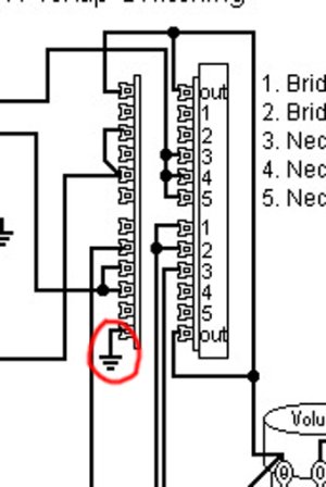
My project guitar is essentially built (with the exception of a few minor details) but I do still have a question and hope someone more knowledgable than I will have an answer. I followed the schematic to the letter but I am not getting hum cancelling in positions 2 & 4. Everything else works as it should. The diagram has a note regarding what to do about it but I can't make heads or tails of the instruction. It doesn't specify which wire, which pup or which terminal. It vaguely alludes to two of those things but without actually making sense to me. I don't know what "the coil tap output" means. Output from one or both of the pups and move it on the switch? Output from the switch? When I compare the partial diagram they show in the special note area and the main diagram, the guitar already has a lead coming from hot on the switch. I don't understand moving it from ground to hot when it's already hot and not currently connected to ground. I think they mean the jumper between to two northernmost terminals should be moved to the other end but the wording is confusing me. Please help me find clarity with this.

Thank you.

wdu_hsh5l11_03_zpse91d696e.jpg
 
Re: Wiring diagram request

I think the picture and instructions are very clear.
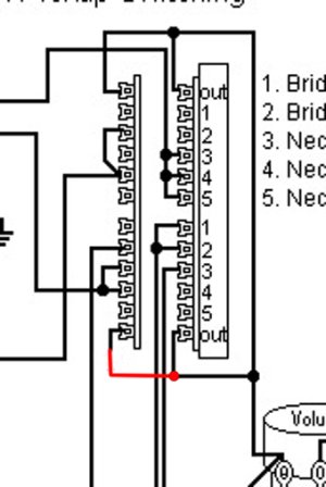
Focus on the two bottom lugs of that switch.
Just jumper the lug labeled with OUT and the lug in same position on the left side of the switch (the other common or pole).

IMHO, taking into account that this is a super-switch, with enough poles and contacts, it should be possible to do it in a neater way but... those instructions should work, anyway.
 
Re: Wiring diagram request

My project guitar is essentially built (with the exception of a few minor details) but I do still have a question and hope someone more knowledgable than I will have an answer. I followed the schematic to the letter but I am not getting hum cancelling in positions 2 & 4. Everything else works as it should. The diagram has a note regarding what to do about it but I can't make heads or tails of the instruction. It doesn't specify which wire, which pup or which terminal. It vaguely alludes to two of those things but without actually making sense to me. I don't know what "the coil tap output" means. Output from one or both of the pups and move it on the switch? Output from the switch? When I compare the partial diagram they show in the special note area and the main diagram, the guitar already has a lead coming from hot on the switch. I don't understand moving it from ground to hot when it's already hot and not currently connected to ground. I think they mean the jumper between to two northernmost terminals should be moved to the other end but the wording is confusing me. Please help me find clarity with this.

Thank you.

The note refers to the ground shown below left circled in red. Disconnect that and make the connection shown in red below right:

detail 1.jpg detail 2.jpg
 
Re: Wiring diagram request

Shall I assume I should also disconnect the ground from that terminal as well before adding the jumper?
(bottom left)

Edit to add:
Beat me to it.
I'll try it and let you know.
 
Back
Top