A pickup physics questions

  • Thread starter Thread starter STGFoley
  • Start date Start date
Re: A pickup physics questions

Sure, but it is the resistance or losses due to the stuff in the circuit (whatever it happens to be). It is measured in ohms because it is virtually the same thing even if it originates from inductive and capacitive losses. The imaginary part (j) is where reactance comes in and affects phase.

Well, because the (j) component doesn't dissipate energy into a non-electrical form (again, in an ideal circuit element, lumped-parameter approximation, etc.), and because it's frequency dependent, the ohm value along the (j) axis -- and the magnitude impedance -- are only meaningful at a frequency for our purposes, since we're usually not doing time-domain analysis. But the energy "loss" is imaginary; you get it back later. It's only in a purely resistive (j = 0) circuit element that energy leaves the circuit in our simple RLC textbook example. So "kinda, but not really".

But yeah, anyone wanting to know more should grab a book. I don't really do phasor math anymore, and we like thinking about real pickups here. And playing them. One parting thought, though: You can usually get a pretty good idea of what's going on in a guitar circuit by looking at pretty simple circuit models based on resistors, inductors, capacitors. As uOpt said, it's mainly simply filters. The trick is remembering that some of the elements are best thought of as combinations of basic circuit elements. For example, a pickup could be thought of as an inductor in series with a resistor, with a capacitor in parallel. Connects to a resistor in parallel (that's your volume control) with a voltage divider wiper, which might connect to another resistor-wipey-thing with a capacitor (depending on how you wire it). A cable is a resistor with a small inductor in series and a capacitor in parallel. The input of an amp might be a resistor with a capacitor in parallel. (There are lots of parallel capacitances in our world; they naturally occur in a lot of the things we build and use, in addition to the actual capacitors that we put in them.)
 
Last edited:
Re: A pickup physics questions

But the energy "loss" is imaginary; you get it back later.

The term imaginary only comes from the fact that you need to calculate the square root of negative voltages which would be impossible mathematically. The effect is really there and presents itself as periodic phase cancellations. But I agree with everything else you wrote!
 
Re: A pickup physics questions

The term imaginary only comes from the fact that you need to calculate the square root of negative voltages which would be impossible mathematically. The effect is really there and presents itself as periodic phase cancellations.

I'm afraid I don't follow. Are we talking about the same effect? And what is the connection between complex impedance and "periodic phase cancellations"?
 
Re: A pickup physics questions

The number of windings (as a function of wire gauge) also affects the physical size of the coil. All things being equal, more windings equals a wider coil, which means the coil senses a larger portion of the string. This in turn affects the frequency response.

To take things further, coils do not need to be symmetrical along the vertical axis.
vc3_4.jpg
(pictures from Throbak pickups, http://www.gundrymedia.typepad.com/)
 
Re: A pickup physics questions

The simplest answer is, all other things being equal (which of course they are not), resonant frequency is proportional to 1/sqrt(L).

Adding turns raises the inductance (inductance is proportional to the number of turns^2) so the resonant frequency goes down proportionally.

This is the first order driver of the response. Other, lesser order, effects may also factor in to modify the response.
 
Last edited:
Re: A pickup physics questions

To understand resonance peak you need to understand the basics of impedance. Impedance is a topic that takes up more than one chapter in most EE text books. I will try to explain and clarify what has been said about impedance and resonance peak in this post already. When I fail here is a link to the AC section of a basic online EE text book. If you really want to understand resonance peak you will want to read the first 6 chapters (the chapters are short).

First impedance is a frequency dependent from of resistance. It comes in two forms, inductive reactance and capacitive reactance. Inductive reactance is associated with coils that form a magnetic field. This includes guitar pickups, choke coils, electric transformers, etc. Capacitive reactance occurs any time two or more electrical paths come close enough with each other to interact (or one path that pass close by itself in one or more places like in the winds of a coil). This includes plates inside a capacitor, wire traces on a circuit board, the wires that make up the windings in a guitar pickup, the windings in a choke coil, etc.

With inductive reactance, high frequencies have a harder time passing then low frequencies. So a bigger inductor will attenuate more highs then a smaller one. Capacitive reactance is the opposite; low frequencies have a harder time passing then high frequencies. So a bigger capacitor will allow more highs to pass then a smaller one.

At his point you may ask: "If a bigger capacitor will allow more highs to pass then a smaller one, why does a bigger capacitor make my guitar sound darker?" It is all in how the capacitor is connected. Electric current always tries find the easiest way to ground (it is actually the pull on the electrons, because electrons flow from ground, but that is a different topic). So when you connect one end of a capacitor to a signal source and the other end to ground, the high frequencies will take the easer path and "bleed off" to ground. If you replace the capacitor in you tone control with an inductor you will "bleed" low frequencies off to ground.

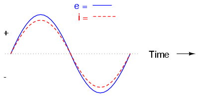
When you look at impedance in a circuit there is a second part of impedance to consider called phase shift. This is where the imaginary numbers come in; I will try to explain without too much math (or any imaginary numbers). If you take a resistor and connect it in a circuit, then send a sin wave through it and measure the voltage and current going through it you, will get a graph like this (E=electro motive force in volts, I = current in amps):

02054.png

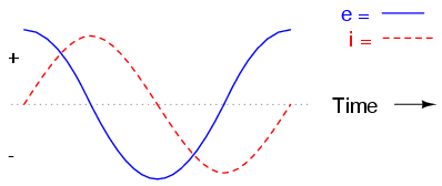
Because current=voltage/resistance the current line and voltage line are in phase (the peaks and 0 crossing points happen at the same time for both current and voltage). If you replace the resistor with an inductor you get a graph like this (E=electro motive force in volts, I = current in amps):

02057.png

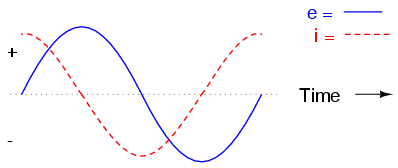
The inductor has caused the current and voltage to become out of phase. To fully understand why is beyond what I can cover here, but it involves math with imagery numbers. The important thing to note is the voltage is leading the current, (the voltage peaks and crosses 0 and the current lags behind). If you increase the size of the inductor you increase the phase shifts. If you increase the frequency of the sin wave you increase the phase shift. If you replace the resistor with a capacitor you get this graph (E=electro motive force in volts, I = current in amps):

02069.png

Again the current and voltage to become out of phase. This time the current is leading the voltage, (the current peaks and crosses 0 and the voltage lags behind). If you increase the size capacitor you decrease the phase shift. When you increase frequency also decrease the phase shifts.

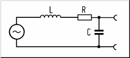
This is all fine and good, but what does it have to do with the resonance peak of my guitar pickups? Obviously guitar pickups have inductance, they are inductors and as I noted earlier anytime you have two or more electrical paths close together (or one path that pass close by itself in one or more places like in the winds of a coil. When you draw an equivalent circuit you get this:

tiefpass-zweiter-ordnung.gif

The sin wave in the circle is the signal source, L is the inductor, R is the DC resistance, C is the capacitance of the coil. The other connectors are where you connect your volume control, tone circuit, and output jack. This is a second order low pass filter. The inductor attenuates high frequency, and the capacitor bleeds highs to ground. Therefor the highs are filtered twice and the low are passed on. In this inductive capacitive circuit something interesting happens. At some point the phase shift of the inductor and the phase shift of the capacitor will be the same, but in opposite directions. This will cause the phase shifts to cancel and it is like the capacitance and inductance are gone. At this point of resonance, a peak will show up in the frequency response.

As you add more windings to the coil you increase both the capacitance and inductance this causes the point where the phase cancels out to get lower. Hope this all makes since.

BTW, the size and shape of the coil will also change magnetic aperture of the pickup (how much of the strings motion is detected by the coil), but magnetic aperture has nothing to do with resonance peak.
 
Back
Top