Dann Huff  wiring + OUT OF PHASE option?

Dennis Ga

New member
Dann Huff  wiring + OUT OF PHASE option?

Hello to all,

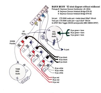
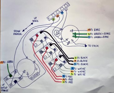
I applied the “Dann Huff” wiring diagram below to a strat without midboost. I am really satisfied with the result.

I'd like to have a extra option "to put the middle pickup OUT OF PHASE with bridge or neck pickup, depending on the 5-position switch"
The pickup should not be split.

Just a CTS 500K push pull DPDT to do the job

1) When PUSHED DOWN = normal working Dann Huff serie/parallel sounds with the 3 toggles
2) When PULLED UP = middle pickup “OUT OF PHASE”


I'm handy with a soldering iron, but not technical when it comes to wiring diagrams.
Please take a moment to help me through this.
I would like to thank you for your time and helpfulness

Dennis from Belgium

translate with Google
 

Attachments

  • James Tyler Dann Huff diagram.jpg
    James Tyler Dann Huff diagram.jpg
    70.4 KB · Views: 0
Last edited:
Phase will likely interact with your series/parallel switches. I believe the series/parallel switches will have to be in series position to work correctly with flipping the phase.. There are plenty of examples of phase switches in Seymour Duncan wiring diagrams and on the web. The hot and ground of the pickup comes into the middle lugs and there is an X pattern the flips them depending on switch position. Just search the diagrams.
 
Phase will likely interact with your series/parallel switches. I believe the series/parallel switches will have to be in series position to work correctly with flipping the phase.. There are plenty of examples of phase switches in Seymour Duncan wiring diagrams and on the web. The hot and ground of the pickup comes into the middle lugs and there is an X pattern the flips them depending on switch position. Just search the diagrams.

Thanks for replay.. So .. the black from 5 way switch middle pickup lug go to E of DPDT, and Green +bare from middle pickup go to B of DPDT. And X go from C to D to 3. And X go from F to A to ground 1. The mini toggle stay untached.
 
The phase should go between the pickup and the 5-way, so I wouldn't tap the black hot off the 5-way and go to the phase switch. It might still work, but I've never tried it that way.

D goes to ground. A or F would go to the 5-way middle pickup lug (or to the volume input lug, if you are tapping the middle lug off the 5-way switch to go to the phase switch).
 
Is this Volume pot + DPDTdiagram correct ?
Where go the bare wire from the middle pu? together with green on DPDT or just ground on back of pot?​

Dann Huff with out of Phase option.jpg
I
 
Last edited:
Instead of having the black lead go from the switch to the left middle lug of the DPDT, I'd wire the black wire from the middle pickup directly to the left middle lug of the DPDT p/p. (So, instead of the wire you labeled as "M PU BLACK" going to the center DPDT, take it to the p/p). Then connect the wire from the right lower lug of the DPDT p/p to the upper left lug of the center DPDT, instead of to the input lug of the Vol pot. That will put the p/p in series with the rest of the wiring instead of in parallel.
 
Guitardoc thanks again..
Is this drawing correct according to your description?

My questions then…
1) My Miidle PU mini toggle functions series/parallel will be retained, now that the wiring go to p/p E lugg ?
2) so...
Pull down = standard Dann Huff (with 3 mini toggles series / parallel)
Pull Up = automatic Middle pu in series (so the M PU mini toggle don't work?) and position 2 and 4 are out of phase. Position 1-3-5 stay standard Dann Huff ?
Is this correct?
If not can you please explain each position correctly?

Translate with google​
Dann Huff with out of Phase-02.jpg
 
Thanks for your input Artie Too,

So far... I read 3 different opinions or I'm reading wrong :)
If not, they probably work, but I don't really know what makes them different.

In replay #3 i read.. Wire the p/p directly from the middle pup. The output from this p/p will go to where you have the "N PU Black" in your diagram. (that’s to the M pu mini toggle ! )

In replay #5 I read.. The phase should go between the pickup and the 5-way, A or F would go to the 5-way middle pickup lug (like your drawing)
BeauBrummels and Guitardoc say --> black M pu directly to p/p E lug. I assume your drawing gives the same result?


In replay #8 again wire the black wire from the middle pickup directly to the left middle lug of the DPDT p/p.

Will I get the following results with your drawing in Replay #11?
1) DPDT down = normal series/parallel function from 3 toggle.
2) DPDT UP =
position 3 = Mid pu in series and out of phase with itself
position 2 = Mid pu in series and out of phase with B pu

position 4 = Mid pu in series and out of phase with N pu

I look forward to your answer.
Dennis
Translated with google
 
position 3 = Mid pu in series and out of phase with itself
position 2 = Mid pu in series and out of phase with B pu
position 4 = Mid pu in series and out of phase with N pu

No, yes, yes. A pickup can't be out-of-phase, (reverse polarity, actually), with itself. Position 2 and 4 are correct.

Edit: Just to be clear, you can reverse the polarity of a pickup by itself, but there's no audible difference. A pickup has no absolute polarity.
 
Thanks Artie, Guitar Doc & Beaubrummels.
As soon as my pickguard arrives I'll start.
I'll let you know how it turns out.​
 
Just wire it according to Artie's diagram.
Sometimes it may seem like two diagrams are different but the result is the same. For example: your diagram in post #9 with post #10 is functionally the same as Artie's diagram in post #11, even though they may look different.
 
I haven't made any progress...
This is the original Dann Huff drawing that works perfectly.
 

Attachments

  • James Tyler Dann Huff diagram.jpg
    James Tyler Dann Huff diagram.jpg
    70.4 KB · Views: 0
The intention is to put middle PU Out of Phase with the DPDT Pull UP =
Position 2: Bridge series + Middle OoF in series
Position 4: Neck series + Middle OoF in series

BUT my attempts with the DPDT OoF connection went wrong, so that even the standard Dann Huff no longer sounds and works properly.
What is wrong with the drawing below?

1) Also the tone knob does not work in any position (if I put a normal pot, without DPDT it does)

2) with DPDT tone pot DOWN, I should get normal series/parallel sound with the 3 mini toggles.
Series and parallel sounds no longer normal (position 2,3 and 4 sounds similar, muddy and noisy).

3) when DPDT tone pot UP and mini toggles are UP (in series) =
- I have no sound in position 3, only heavy noise.
- Positions 1 and 2 sound the same (and sound as they should sound in series with the DPDT down.
- Also Positions 4 and 5 sound the same (and sound as they should sound in series with the DPDT down.

4) There is clearly a connection problem with that DPDT and middle pu, there is also a grounding problem with the middle PU.

Who can help me?
I will certainly appreciate it.

Translated with Google
 

Attachments

  • 20240124_170706.jpg
    20240124_170706.jpg
    87.5 KB · Views: 0
Back
Top