Help me troubleshoot this pedal

cohara41

New member
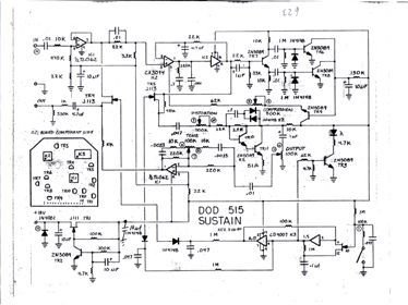
Sustain 515A.jpg For some reason my DOD Sustain 515A gives almost no outout. When I crank the amp with high gain you can hear a litle output. If anyone has any experience with this type of problem & can guide me thru troublshooting I'd be thankful for the help or guide me to the help. I know how to use a multi-meter but no real electronics experience. Thanks in advance......C
 
Re: Help me troubleshoot this pedal

C:\Documents and Settings\Owner\Desktop\DOD515.pdf
Chris, does this help????
 
Last edited:
C:\Documents and Settings\Owner\Desktop\DOD515.pdf

C:\Documents and Settings\Owner\Desktop\DOD515.pdf

Chris, I'm hoping this works.
 
Re: Help me troubleshoot this pedal

Well, unless you have a signal tester, and an idea of what voltages are supposed to be where then the best we can offer you is....there is a short, or a component on this somewhere that isn't working properly.

Unless of course you are tying to build one yourself and are wondering if this particular schematic will result in a working pedal.
 
Re: Help me troubleshoot this pedal

AlexR, I don't have a signal tester only a volt meter, I'm not sure if that's enough. I'll contact the person from DOD that sent me the drawing & ask a bunch of questions. Thanks for looking.
Chris of Arabia, thanks for resizing the drawing. Hopefully I'll get this old pedal working again. Cheers....
 
Re: Help me troubleshoot this pedal

Tech from DOD says "it's hard to tell but probably a processing chip & they no longer have parts". That's a bummer. Does anyone know if there might be another source for chips for this pedal. Sounds like it may be a paperweight. Cheers...
 
Re: Help me troubleshoot this pedal

if you open the pedal up
the processing chip is the black rectangle with many legs
the part soldered to the board is the base
the chip lifts out
there are some numbers on top
those identify them
put those numbers into a search engine to find a aftermarket vendor
 
Re: Help me troubleshoot this pedal

if you open the pedal up
the processing chip is the black rectangle with many legs
the part soldered to the board is the base
the chip lifts out
there are some numbers on top
those identify them
put those numbers into a search engine to find a aftermarket vendor

Ehdwuld, thanks Dude. that's great info I wasn't aware of. I'll do that & hopefully this pedal is saved. Have a great day............
 
Re: Help me troubleshoot this pedal

The IC types are actually written on the circuit diagram as follows:

IC1 = TL062 - main power supply goes in on pin 8, but also on pin 3, though the circuit looks as if there is a voltage divider on the way to that pin

IC2 = CA3094 (could also be LA3094 depending on how you read the diagram) - main power supply goes on pins 7 & 8

IC3 = CD4007 - main power supply goes in on pins 2 & 14

I know the CD4007 is a Texas Instrument chip as I was looking at a spec sheet for it earlier. If I'm reading it correctly, it's expecting to see anything between 5v and 15v to operate - most likely +/- 10v. Though I've not looked at the other spec sheets, IC1 and IC2 probably have similar requirements.

Before you go pulling things apart, do some power supply measurements to check the chips are getting a decent supply. Try as follows:

a) External power supply before connection - according to the diagram, the pedal is expecting to see 18v. This may be AC, as the first part of the circuit looks like it is power conditioning

b) Connect up the power supply (inc. 1/4" jack in input socket to complete the earth return for the power circuit). Measure the voltage again as soon as possible after the power socket, but before TR1. The voltage should be almost as you got in a), but may be a little lower because there is now a load on the power supply

c) Measure the voltage immediately after TR1. It may be the same as we got at b), possibly lower depending on how the power conditioning was designed to work

d) measure the voltage on the IC power pins as identified above. They should all show the same voltage as you got at c), with the exception of pin 3 on IC3 which I think should be something less.

At least by doing that, you should know what the power supply around the pedal is doing. If you are getting very low measurements inside the pedal (i.e barely above 0v), but with a known good power supply, then there's the possibility that something has shorted out inside there.
 
Re: Help me troubleshoot this pedal

Chris, thanks, I'll give it a major checkout as soon as I get home. I think the 18 Volts is DC because you can use two 9 Volt batteries instead of the plug in transformer. This is some detailed troubleshooting steps, I'll go over it slowly for sure & let you know what I find. Thanks again for all the time you've put into. Cheers....
 
Re: Help me troubleshoot this pedal

Power supply is 20 V DC from the transformer. IC1 Pin 8 3V DC after TR1, Pin3 0V DC. IC2 Pin 7&8 3V DC. IC3 Pin2 0V DC, Pin 14 20V DC. Pin 4 is 12V DC which is on IC1, 2 & 3. I'm counting 14 pins as it says on the pc board drawing. Hope these nunbers help. Cheers
 
Re: Help me troubleshoot this pedal

I'd go straight to TR4 J113 [Mosfet]
It combines your dry/straight through signal with the sustained signal and out puts them. If you can hear a faint sound my guess is it's shot.
Does the faint sound have sustain in it ?
 
Last edited:
Re: Help me troubleshoot this pedal

GV, Pin one I believe has 0 Volts DC ( I'm at work now ). The sound seems to have sustain, compression & distortion when played but this is with the amp cranked & the gain cranked. I've got 12 volts DC on pin 4 which is ground so something is shorted. I need to get a digital MM to check out the diode right after pin 13 that's 20 volts DC. Thanks for lookin'.....Cheers....
 
Re: Help me troubleshoot this pedal

If it appears to be working although it is very soft, your chip is fine. Again TR4 is the output transistor for it. It''s the last one in the chain before the output plug and the most likely culprit for your lack of sound.

Mosfets are usually cheap and readily available from electronic component suppliers/shops. I'd just go get a replacement and try it. you've got nothing to lose other than a couple of dollars.

I'm presuming you have a soldering iron and know how to solder.
Having a Multi meter is a good idea. You could use it to test the transistor.
A lot of multi meters these days have " transistor test " sockets on them.
 
Re: Help me troubleshoot this pedal

GV, Pin one I believe has 0 Volts DC ( I'm at work now ). The sound seems to have sustain, compression & distortion when played but this is with the amp cranked & the gain cranked. I've got 12 volts DC on pin 4 which is ground so something is shorted. I need to get a digital MM to check out the diode right after pin 13 that's 20 volts DC. Thanks for lookin'.....Cheers....

Apart from your power in pins and grounding pins on your chips, there's not a lot of point testing them when active. IC1 is a buffer chip. The other two do most of the rest [ sustain , etc] along with a couple of the transistors.
 
Re: Help me troubleshoot this pedal

GV, I'll check TR4 for the faint hissing sound. I've got the soldering covered, just need to get a better miltimeter to check diodes & transistors. Thanks again.....C
 
Back
Top