HH to 5-way wiring Q

Weekendwarrior

New member
IMG_3945.jpg
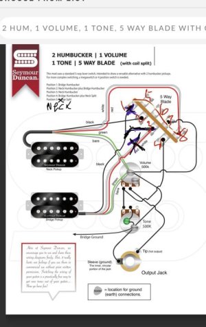
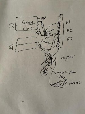
Greetings I am new to this forum. Hopefully I am in the right place for this question about wiring. I am doing a parts build and have come in to one Seymour Duncan neck humbucker with typical 5 wires and one Gibson humbucker with two. To make the most of the Seymour Duncan I want to wire them both to a 5-way import blade switch and have positions whereby: 1. Bridge humbucker, 2. Neck humbucker, 3. Neck and bridge humbuckers. 4. neck split and bridge humbucker and 5. neck split on its own. I couldn’t find a diagram. I altered this one from SD and am hoping someone can weigh in on whether it looks right.
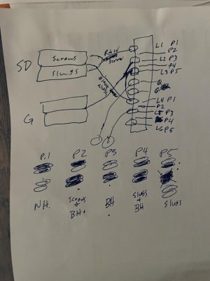
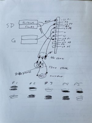
In case my sketch is difficult to translate, I tried to show that:
1. On the bridge pick up the Gibson Hot wire would go to lug 3 (and there is no red and white wire)
2. The red and white wire on the SD neck pick up would be jumpered from lug 8 to lug 1. Additionally I have an import 5 way switch with 8 lugs. Any help on n translating from fender to import switch would be greatly appreciated. Thanks very much
 
Hello!
This is what I see in your diagram with 5 being the switch towards the nut and 1 toward the jack end.

5: Bridge HB
4: Bridge HB & Neck HB split Screw Coil
3: Neck HB
2: Neck HB Split Slug Coil
1: Neck HB split Screw Coil

I don't know your experience level but if you're just starting to work with Strat style 5 switches they're not very intuitive. This page is a fantastic illustrated explainer of how they work. It's a 2 pole 3 position switch mechanically hacked to make 5 positions. https://www.seymourduncan.com/blog/latest-updates/5-way-strat-switch-explained-part-1

Position 2 and 4 aren't independent. Pos 2 is 1 and 3 connected; 4 is 3 and 5 connected. There's creative ways to use that connection but its also very limiting.

Off the top of my head I don't see a way to do what you're looking for on a standard 8 lug Strat switch. It might be possible with this 12 lug 5 way switch where each position is fully independent. If not that, then the 4 pole 24 lug super switch can do it

 
Thanks very much switchman that’s enormously helpful info. I have done basic wiring on 3 and 5 way, but always following a schematic. Am I reading the lug positions on this diagram correctly? Here is the pic again with the lugs numbered.
 

Attachments

  • IMG_3945.jpg
    IMG_3945.jpg
    49.8 KB · Views: 0
Hello!
This is what I see in your diagram with 5 being the switch towards the nut and 1 toward the jack end.

5: Bridge HB
4: Bridge HB & Neck HB split Screw Coil
3: Neck HB
2: Neck HB Split Slug Coil
1: Neck HB split Screw Coil

I don't know your experience level but if you're just starting to work with Strat style 5 switches they're not very intuitive. This page is a fantastic illustrated explainer of how they work. It's a 2 pole 3 position switch mechanically hacked to make 5 positions. https://www.seymourduncan.com/blog/latest-updates/5-way-strat-switch-explained-part-1

Position 2 and 4 aren't independent. Pos 2 is 1 and 3 connected; 4 is 3 and 5 connected. There's creative ways to use that connection but its also very limiting.

Off the top of my head I don't see a way to do what you're looking for on a standard 8 lug Strat switch. It might be possible with this 12 lug 5 way switch where each position is fully independent. If not that, then the 4 pole 24 lug super switch can do it


Thank you again, I should also ask is there a way to have position 4 or any of the positions be bridge HB and neck HB and another position be bridge HB and one of the neck splits?
 
Most wiring diagrams refer to the lugs like this. It shows which lugs are grouped together or related instead of just a sequence. Thinking of it this way makes getting a handle on how to modify diagrams easier. It makes more sense on a 3 way switch because 1,2,3 correspond to where the switch is. In position 1, A1 is connected to A0 and B1 is connected B0, but A and B aren't connected to each other) and so on. Sometimes A and B are flipped, or the number direction is reversed meaning 1 the neck pickup and 5 is the bridge. But the idea is the same.

​​image.png


The 5 way positions correspond this way. P2 is 1 and 2 and P4 is 2 and 3 connected etc.

image.png


I noodled with a diagram briefly. You can get the neck split in some position alone or with bridge, but I don't think all 5 of the sounds you mentioned in the OP. I'll take a look again later and see what I can find out there already or come up with.

Since you have a dual coil (humbucker) neck pickup and a non-splittable bridge pickup, you may want to look at diagrams for a Tele Custom. Your bridge pickup is a humbucker but you'll be wiring it like a single coil

​​
 
Most wiring diagrams refer to the lugs like this. It shows which lugs are grouped together or related instead of just a sequence. Thinking of it this way makes getting a handle on how to modify diagrams easier. It makes more sense on a 3 way switch because 1,2,3 correspond to where the switch is. In position 1, A1 is connected to A0 and B1 is connected B0, but A and B aren't connected to each other) and so on. Sometimes A and B are flipped, or the number direction is reversed meaning 1 the neck pickup and 5 is the bridge. But the idea is the same.

​​


The 5 way positions correspond this way. P2 is 1 and 2 and P4 is 2 and 3 connected etc.


I noodled with a diagram briefly. You can get the neck split in some position alone or with bridge, but I don't think all 5 of the sounds you mentioned in the OP. I'll take a look again later and see what I can find out there already or come up with.

Since you have a dual coil (humbucker) neck pickup and a non-splittable bridge pickup, you may want to look at diagrams for a Tele Custom. Your bridge pickup is a humbucker but you'll be wiring it like a single coil

​​

Thank you very much that makes a lot of sense. Thinking of the bridge as a single coil (since it can’t be split) helps conceptually for sure. I’ll take a look for tele custom wiring, and I am obliged for any additional al ideas or guidance you may have.
 
Sooo... existing wiring diagrams for a splittable humbucker and a single coil or non-splittable humbucker are uncommon. I did find another old thread on ultimate guitar that hit a similar dead end - the standard 5 way switch is just too limited. I also found the SD diagram you started with had a gltich in position 4.

If you really want those 5 sounds, this more advanced switch can do it with for about $14 on eBay .... Fender 5-Way, 12-Lug Oak-Grigsby 5-Way Lever Control Switch, 003-9003-049

Thanks for the lead on the fender switch. I’ve been looking as well for tele custom wiring diagrams in the basic configuration I’m hoping to get.
what is the position 4 glitch you see?
 
I have been reading up and think I have a better overall understanding.@switchman thank you for the resources. I am going to be using an import switch. Here is a switching and pickup diagram I sketched. If I understand that positions 2 and 4 are just combos of 1&3 and 3&5 respectively I don’t think everything I can all the options I had in my OP. Any feedback greatly appreciated on whether this looks right.
 

Attachments

  • IMG_3956.jpg
    IMG_3956.jpg
    38.4 KB · Views: 0
what is the position 4 glitch you see?
The way that SD diagram is drawn P4 will be both humbuckers split - Neck Slug coil and Bridge Screw coil. Not Bridge full HB and Neck split.

I missed earlier that you said import switch. I don't have one in hand but from what I found online you have the lug mapping correct. But it still has the same limitations as the Fender switches.

It will be difficult for anyone to comment on the pen diagram other than saying its incomplete. The wires from Lug 0 and L5 are going to unlabeled circles. Is one hot output and one ground? If so which is which? The pickup ground wires are also missing. Both of these items are crucial to tell what's going to happen in each switch position.

Thanks very much. I took another crack at it with greater detail. I have not been able to figure out a way to get all of the combinations sought in my OP. This diagram of it if correct gets a lot of what I was hoping with the main loss being full humbuckers neck and bridge together. Any guidance appreciated as to whether what I have looks like it will work and if there is a way to wire it somehow to get the full HH in one of the positions. Thank you again.
 

Attachments

  • IMG_3957.jpg
    IMG_3957.jpg
    36.8 KB · Views: 0
Last edited:
Update: I wanted to get away with not drilling a hole but to get the tones I want I am going to add a dpdt on/off/on to the neck coil and go straight to the existing 3-way switch. The shallow electronic cavity did not allow for a super switch. For the sake of posterity I’ll draw up a diagram, and welcome any feedback. Thank you @switchmaster for your help!
 
Great. This stock diagram does almost exactly that. The only changes are to wire the neck mini-switch the same way the volume push pull is wired, and ignore the bridge coli split leads your pickup doesn't have and tone push pull wiring.

image.png
 
Also for reference, here's what's actually going on in the last pen diagram for P1 and 2. Colored lines trace the flow from the jack hot or tip lug to ground by the shortest path. From there it returns to the ring or ground side of the jack to complete the circuit (that's omitted for clarity). Look for places it splits to more than one path to ground (shown in different colors). This happens on every guitar with standard treble rolloff tone control which is connected in parallel by design. The grey dots show where these parallel path splits. In this diagram the Black lead from the neck humbucker isn't in the circuit in P1. Internal wiring of the bridge humbucker is omitted for simplicity. You can carry this idea forward for the other 5 positions. Electronics engineering text book theory that covers powered (active) circuits will give a 100 times more in-depth explanation about electrons, transformers, and other components than this. For the purposes of deciphering passive guitar circuits this method is sufficient.

sdf.jpg
 
Also for reference, here's what's actually going on in the last pen diagram for P1 and 2. Colored lines trace the flow from the jack hot or tip lug to ground by the shortest path. From there it returns to the ring or ground side of the jack to complete the circuit (that's omitted for clarity). Look for places it splits to more than one path to ground (shown in different colors). This happens on every guitar with standard treble rolloff tone control which is connected in parallel by design. The grey dots show where these parallel path splits. In this diagram the Black lead from the neck humbucker isn't in the circuit in P1. Internal wiring of the bridge humbucker is omitted for simplicity. You can carry this idea forward for the other 5 positions. Electronics engineering text book theory that covers powered (active) circuits will give a 100 times more in-depth explanation about electrons, transformers, and other components than this. For the purposes of deciphering passive guitar circuits this method is sufficient.


Thank you very much that’s very informative! Though I am not getting to use the 5-way on this build, I have learned a lot finally about how a five way switch actually works. It will come in handy at some point I am sure.
 
Sounds good. I should clarify one point since I can't manage to edit the post.

it should say "From there it returns to the sleeve or ground side of the jack to complete the circuit"...not to the ring.
 
Finished: I completed this project by wiring with a three way switch and a DPDT on/off/on. The guitar works as I hoped exactly. The dpdt mini toggle (based on SD article) is wired so that the SD splittable neck pickup is selectable for full humbucker, slugs alone, and screws alone. The Gibson Smoky coil bridge pick up is not splittable. Here are some pics:
1. My drawn wiring diagram (I think it is correct to what I did)
2. Pics of the wiring diagram references I used (in addition to that which switchman provided
3. pics of the actual electronics cavity
4. pics of the finished guitar
 

Attachments

  • IMG_3983.jpg
    IMG_3983.jpg
    46.5 KB · Views: 0
  • IMG_3960.png
    IMG_3960.png
    94.6 KB · Views: 0
  • IMG_3981.png
    IMG_3981.png
    144.6 KB · Views: 0
  • IMG_3971.jpg
    IMG_3971.jpg
    66.3 KB · Views: 0
  • IMG_3978.jpg
    IMG_3978.jpg
    60.5 KB · Views: 0
  • IMG_3972.jpg
    IMG_3972.jpg
    62.7 KB · Views: 0
  • IMG_3970.jpg
    IMG_3970.jpg
    50.3 KB · Views: 0
  • IMG_3969.jpg
    IMG_3969.jpg
    76.6 KB · Views: 0
  • IMG_3976.jpg
    IMG_3976.jpg
    54.6 KB · Views: 0
  • IMG_3977.jpg
    IMG_3977.jpg
    66.5 KB · Views: 0
Sounds good. I should clarify one point since I can't manage to edit the post.

it should say "From there it returns to the sleeve or ground side of the jack to complete the circuit"...not to the ring.

Thanks very much again for all of your generous help. I got the work done and I am glad I learned much more about 5-ways through this effort. The mini toggle looks fine and does what I hoped.
 
Correction I didn’t show in the pics that the tone pot is grounded to the volume pot. Here is the updated diagram
 

Attachments

  • IMG_3983.jpg
    IMG_3983.jpg
    46.7 KB · Views: 0
Back
Top