jimmy page wiring diagram help

joekelly9692

New member
Hi everyone.this is my first post........i recently installed a set of whole lotta humbuckers wired jimmy page style and it workedout great.......but could someone please clarify something for me. on the diagram, the bridge volume pot has two blobs of solder.....the larger blob has no grounds connected to it so could someone tell me what this ground is for........many thanks for any help........joe............
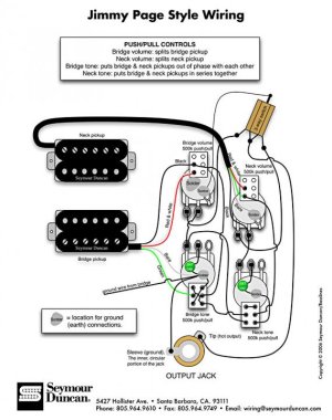
jp_style.jpg
 
Re: jimmy page wiring diagram help

Yeah, probably just something left over from a different circuit. You can safely ignore it!
 
Re: jimmy page wiring diagram help

yea it is something that left - but on this diagram there is no connection between all solders volume to tone tone to ground.
Please dont forget to connect the ground to all solders!!! (star mode).
Mainly someone can assume that connection is done through the housing and grounded cavity but there is no cavity drawing on the diagram!!!
Dont forget to solder all housing pots together to the ground!!!
 
Re: jimmy page wiring diagram help

If there isn't a metal bridge plate that the pots are mounted to, have a wire connecting every pot casing to ground.
 
Re: jimmy page wiring diagram help

that was my case - I dont know exactly if there is a metal plate and dont know If our User have this metal plate so I am only remaining - to connect all the pots together.
:)
 
Re: jimmy page wiring diagram help

great help guys........thanks a bunch.......when i done this wiring on my epi les paul exactly as the diagram it worked perfect.......now i have tried it on my 2013 gibson lp standard its not working...........mmmmmm
 
Re: jimmy page wiring diagram help

I told. Try to check if your wiring is connected properly.
Use multimeter put it to a hot and ground part of jag.
Verify the reaults when changing mods.
Do multimeter works in every config positions?
 
Hi everyone.this is my first post........i recently installed a set of whole lotta humbuckers wired jimmy page style and it workedout great.......but could someone please clarify something for me. on the diagram, the bridge volume pot has two blobs of solder.....the larger blob has no grounds connected to it so could someone tell me what this ground is for........many thanks for any help........joe............

View attachment 49482

I have the original diagram from the Seymore Duncan (not forum) website before it was taken down... the extra blob on the diagram you originally posted about was definitely not on the original diagram. A lot of other things are drawn slightly differently, although the overall diagram is nearly identical, the ways the individual components are depicted are somewhat different. There are some notable differences though... the two tone control pots are grounded to each other, the bridge tone control switch upper left and lower right contacts are jumpered to each other, even though in your diagram it looks like they also might go to the left middle switch contact (common sense would inform you that wasn't the case). On Seymour's drawing the pot shells are grounded going from the bridge volume to the bridge tone to the neck tone to the bridge volume. The rest of the diagrams look pretty much identical to each other.
 
Last edited:
Back
Top