Megaswitch M + Liberator

Let me double check my diagram. I believe it's good as it is, but I'll check.

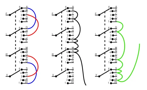
Do you have a meter? If you do, place the handle all the way back in the "bridge" position. Then verify that one of these connections is shorted. You only need to verify one pair. If its good, the other three will be also. Just do the one that's easiest to get to.

F to E, L to K, R to Q, or X to W.
I don't have a meter. That's why I’m asking.
 
I don't have a meter. That's why I’m asking.
And I don't have the switch in my hand. Let me study some Schaller literature and see if I can figure it out. It's important that we get it right.

P.S. I don't know if you want to go to the trouble, but a simple battery and LED or lightbulb would do the trick.
 
You know . . . I just wasn't thinking. This is easy peasey. The pickups will be connected with the screw terminals. So, if after you get it all wired up, and it turns out to be backwards, (neck selected in bridge position), you'll just reverse the wires in the screw terminals. Should take maybe five minutes, no soldering.

I'll get that diagram up shortly.
 
You can start with this. Take the Megaswitch out of the guitar to make it easier to solder to. Add all these jumpers in three stages.
 

Attachments

  • megaswitch_jumpers.webp
    megaswitch_jumpers.webp
    52.4 KB · Views: 4
You can start with this. Take the Megaswitch out of the guitar to make it easier to solder to. Add all these jumpers in three stages.
That is a lot of jumpers. I'm assuming those are the colours of the Liberator, correct? If so, is blue actually white? For the black & green, could I strip the wires of the pot itself and solder without fully cutting them? I ask because I don't have that many loose wires, I'd have to buy them. Though I suppose I should find out where they're sold here 😂

Also, if I’m jumping sequential connectors, e.g. L+M, can I just use extra solder to make a large blob? Or do those need actual external wires?

Also also, am I connecting F to A, L to G, R to M, and X to S? Or are those connections already in the PCB itself?

Why did I choose THIS as my first soldering job 🤦‍♂️
 
No. Colors are just for clarity. Use any colors you want. I recommend some decent 22 gauge wire, like this: Guitar Wire

But anything will do. Just don't use anything too large.

These aren't the Liberator wires. These are just jumpers. I'll show the Liberator wires in the next installment. I'm just double-checking it so I don't screw you up. But those jumpers are correct. The extra "flying lead" on the green and black aren't really necessary now. They can be installed later.
 
I was looking for an explanation for the Liberator terminals, and it's a bit crazy not just that it always comes back to this forum, but to you two specifically 😂 I found what I needed (i.e. the I/O/G pinout equivalent for the 4 back terminals) on another thread.
SD needs to add more resources on the website.

I'm planning on wiring everything this week, but I think I do need to get some leads first. The pdf schematics on the Schaller website are very confusing to read.
To be fair, we have a couple of amazing experts with that sort of thing here, and yes, the main website could use some better explanations of some things. I have a Liberator here that I got as a prototype when it first came out, but I had no idea how it worked, and the few times I looked on the website, I couldn't find the info.
 
You can start with this. Take the Megaswitch out of the guitar to make it easier to solder to. Add all these jumpers in three stages.
Since you haven't sent the rest of the diagram yet, I think I’m going to do the HH8 wiring instead (bridge series, bridge parallel, both pups, neck parallel, neck series). That one doesn't require modification, and position 2 might even be more usable. I just need to figure out the colour code 😅 I’m also going to get copper tape and a meter.

Side note, for a different project: why is it so difficult to find on/on/on mini toggles? Or is this a Brazil problem? For some reason I can only find on/off/on. I can't wait to leave this country.
 
i think we have pretty easy access to things here is the usa most of the time. though costs are through the roof on a lot of things made overseas right now
 
Back
Top