ThreeChordWonder
New member
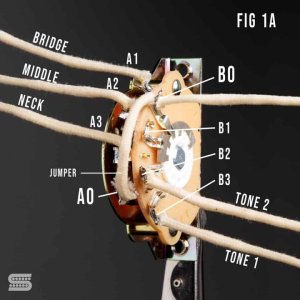
On a standard Fender 5-way switch there are four lugs on each side.
The switch was originally designed - badly - to be a three-way, which gave bridge, middle and neck, but was not intended to enable bridge plus middle or middle plus neck.
Musicians found, however, that they could make the "wiper" contact span two lugs at once, thus giving two intermediate switching options, bridge plus middle and middle plus neck.
Fender responded by adding two extra notches to give us the switch we have today.
Now. On each bank of four contacts, one us the common or "out" lug, and the three pickups get wired to one ach of the other three "ins".
It doesn't matter which side of the switch is used.
BUT:
the contacts on one side of the switch are NOT connected at all to the contacts on the other side.
AND:
The common or "out" lugs are located at opposite ends of the sets of lugs, so one might be bottom left as you look at the switch, the other top right.
To make your tones connect you have two fundamental choices.
You can either go the original 1950s Strat way and allocate one tone to one pot, the second to another, and leave the third (usually the bridge) with no dedicated tone control at all..
Or you can allocate one tone to one pickup and the other tone pot to the other two.
If you go the first way,, just solder the "outs" to the tones to the respective "ins" on the switch and don't bother with the other side of the switch.
If you wire the tones to the bridge and neck, you'll actually get active tone controls in P1, P2 on one tone pot, P4 and P5 on the other, as the pickups connect in parallel in P2 and P4. In P3 you'll get no tone control, however.
If you wire the tomes to neck and middle, you'll have active tone controls in P2, P3, P4, and P5, but not in P1 (bridge only). In fact in P4 both tone controls will be active.
Now. If you want to allocate one tone to one pickup and the other to the other two, you'll need to use the second side of the switch.
Start by soldering a jumper diagonally across the switch linking the two common lugs.
Next decide which tone pot will serve which pickup(s).
Let's say you want one tone for the neck and middle and the second for the bridge. This works well for HSS setups because you can use one tone pot resistance and capacitor for the single coils and a different one for the humbucker, BTW.
Solder the tone pot wire for the neck and middle pickup to the lug that is "hot" when you select P5 (neck). Solder a wire "jumper" across to the next door (middle pickup) lug. Solder the second pot to the last remaining (bridge) lug.
If you want one tone pot to serve the neck only and the other to serve the middle and bridge, just move the jumper wire accordingly.


