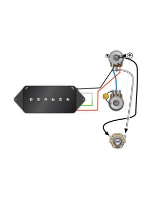
P90 Stack Wiring Diagram for a Junior

MarkG

New member
G'day I need help figuring out how to wire a P90 stack in a LP Junior (One Volume one Tone). I don't want a pull pot, I just need the best way of wiring this for a Junior. I tried wiring as per the SD diagram for one pup but that just gave me 7.7 k or half the output of one coil. (so I'm assuming that's the parallel wiring) I tested both coils separately and they both output around 15.5k each (which would mean 31k in total, which is what the pup is rated as in the specs). Probably don't need that much (who does) but I'd settle for 15 k. Any tips or recommendations on how to do this? Thanks in advance.
 
I may be missing something but it seems impossible that the p90 stack would come in at 31K total...

But, if as you suspect you are in parallel, you just need to change The output of the first coil in the input of the second coil. Instead of signal splitting into each coil, the output of the first coil is the input to the second coil... Resulting in input to first coil output to second coil and the output from the second coil completing the circuit.

I've never messed around with this pickup so maybe I'm missing something weird. Come in
 
The wiring permutattions of this pickup are seriously doing my head in.
Long and detailed responses as follows:

Erik,
Welp, the total DCR is in fact 31.6k.

https://www.seymourduncan.com/single-product/p90-stack

Those should wire back/red to hot, green/white/bare to ground. This is the only diagram I could find with P90 stacks so assuming that is series.

https://www.seymourduncan.com/images...K_3G_2V_2T.jpg


That's the way I initially did it, but only got 7.7k which is a third of the total output.
(But that's what it should be if two 15.5k coils are wired in parallel.)


Zionstrat
I may be missing something but it seems impossible that the p90 stack would come in at 31K total... [/QUOTE said:
Everybody says that, even I said that,
but like Erik points out it is indeed 31k as per the product spec data.

Anyway, I tried wiring it in series as you suggested and got over 30k on the mmeter, but then how do I actually wire that to the pot?

I'm thinking the green and white get joined and taped off, while the red and black go to the hot and ground lugs of the pot.
That leaves me with the spare bare wire. If I ground that too, that seems to work according to the multimeter.

It's possible something got wired backwards internally. Reach out to the support team for verification. But yes, the bare wire goes to ground, always.
 
OK I wired it up like this. See pic.
North finish (grey) and South Start (green) are wired together.
That leaves me with North start (black) and south finish (red) as the two connection wires.
The thin blue line from the pickup is the bare wire.

Seems to work, I get just under 30k output at the jack.

my p90 stack.jpg
 
The Duncan diagram shows green, white, and bare going to ground, and red/black to hot. That implies they were intended for parallel wiring. If you want to go series, technically, you should reverse your red and green. This also assumes they were wired correctly internally.

You can check the polarity with a meter if you have one. Do you?
 
Back
Top