Pickups soldered to toggle switch?!

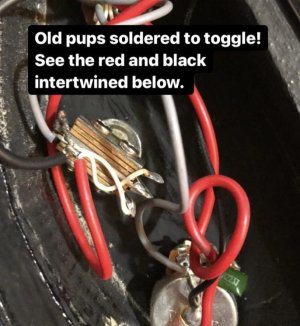
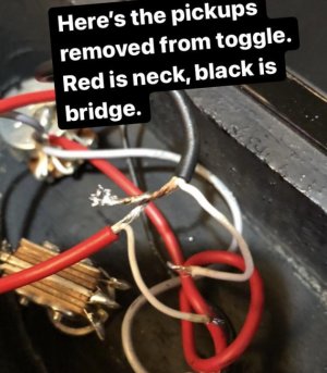
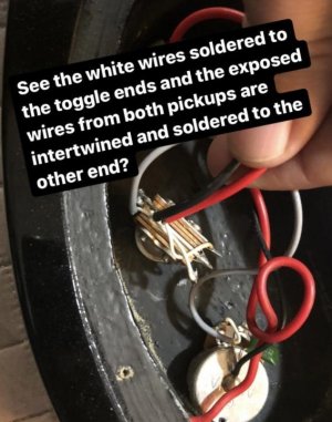
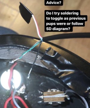
Stock pickups in Kramer Pacer 202s were soldered to toggle switch, white wires to ends of toggle, thicker exposed wires from each pickup intertwined and soldered to the other end of toggle.

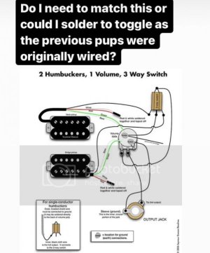
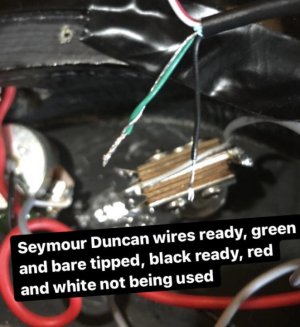
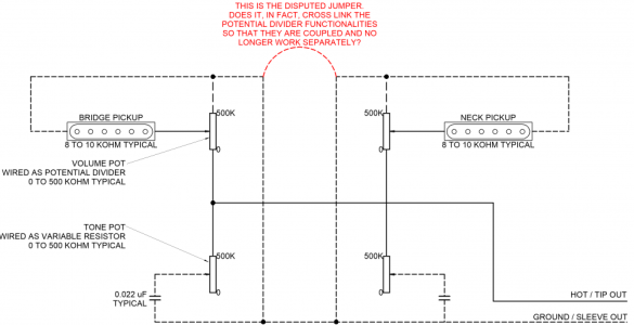
Putting in Seymour Duncan JB and Jazz (no splitting so red and white not used). I could follow SD diagram though it doesn’t match what I see going on. Could I just solder to toggle like the previous setup was? And if I did that, which wires would intertwine (the greens and bares?) and which would I solder to toggle ends (the black ones?)

Thanks everyone!
 

Attachments

  • photo104505.jpg
    photo104505.jpg
    66.4 KB · Views: 0
  • photo104507.jpg
    photo104507.jpg
    59.3 KB · Views: 0
  • photo104506.jpg
    photo104506.jpg
    60 KB · Views: 0
  • photo104510.jpg
    photo104510.jpg
    51.1 KB · Views: 0
  • photo104509.jpg
    photo104509.jpg
    49.9 KB · Views: 0
  • photo104508.jpg
    photo104508.jpg
    55.6 KB · Views: 0
i think the sd diagram is identical to the current wiring, except that the pickups' ground wires are soldered to the ground tab on the toggle switch, rather than directly to the potentiometer. In the end it doesn't really matter since it's getting grounded either way.

so the duncan hot leads (black) will go where the stock pickups' white wires were, and the duncan ground leads (green and bare) can either go to the other side of the toggle switch, or to the back of the pot, like in the diagram.
 
You are awesome, thanks so much! I was thinking the black wires would go where the former white ones were so I appreciate somebody confirming that. Should the green in bare wires the inner twined Or no?
 
I would intertwine and solder the green and bare wires together, but don't intertwine the green and bare wires of one pickup with the other pickup's, because if you ever decide to swap a pickup in the future it will be difficult.
 
Just be aware that your switch and the switch in the Seymour Duncan diagram are not the same...the ground connection and the hot output are on the opposite ends.

I don't know why SD diagramed the switch like that, I have never seen a toggle made like that. Every one that I've ever seen has had the switch output connection (where the two tabs are soldered together) on the same end as the input tabs and the ground tab is on the opposite end...just like the switch that you have in your guitar.

Switchcraft toggles switches are like the one in the diagram, and they're pretty much the industry standard for American made instruments so it makes sense.
switchcraft_toggle_switch__86204.1530215985.jpg?c=2.jpg
 
Switchcraft toggles switches are like the one in the diagram, and they're pretty much the industry standard for American made instruments so it makes sense.

Thanks for pointing that out to me. That's interesting. I've used Switchcraft before (a long time ago, admittedly) and don't remember that. However, every, EVERY other mfr. that I'm aware of makes them the same as the OP's. Even Switchcraft's Right Angle "L-Type"Toggle has the input and output tabs on the same end.

Switchcraft may be, as you say, the "industry standard" but by sheer number of switches made, they are by far in the minority. You are more likely to find the configuration like the OP's.

Nevertheless, my only intent on my post was to caution the OP to make the output and ground connections on the correct tabs on HIS switch and to not blindly follow the diagram.
 
Just follow the SD wiring diagram and adapt it to suit your particular switch configuration.

If you have two volumes and two tones and you're wanting independent volumes:
  1. Solder the hot out (usually black on SD humbuckers) to the MIDDLE lug on the pot.
  2. Looking at the back of the pot with the lugs pointing towards you, wire the left lug to the switch.
  3. The right lug gets grounded.
  4. Solder the green and bare wires from the humbucker to the back of that pickups's volume pot.
  5. The red and white wires get soldered to each other. If you don't want coil splits, just insulate the ends. If you do want coil split, Solder the red and white pair from each pickup to a separate common lug on a push-pull and ground the lug corresponding to the pull connection. You can solder an extension wire to each red and white pair if you need to.
  6. Wire each tone pot hot to either the pickup input lug on the pot (modern wiring) or the output lug (classic or 50s style wiring). Your choice.
  7. Ground each volume pot to its respective tone pot, but DO NOT ground the two volume pots to each other. Don't ask medon't. I haven't got a clue, but dont.
  8. Ground each tone pot to the other.
  9. Ground the switch ground and output ground wire to one of the tone pots.
  10. You may need treble bleeds as well. Your ears, your choice.
if you only have a single volume and a single tone, wire the pickup hots directly to the selector switch input and wire the volume and tone pots Telecaster style.

If you have two volumes but only one tone, wire up for independent volumes as above, but wire the single tone pot in parallel with the output wire to the jack.
 
Last edited:
[*]Ground each volume pot to its respective tone pot, but DO NOT ground the two volume pots to each other. Don't ask medon't. I haven't got a clue, but dont.
[*]Ground each tone pot to the other.

OK, so I WON'T ask you why because there can be no intelligent answer to support such a statement..
By grounding each vol pot to it's tone pot, and then grounding each tone pot to the other, you absolutely HAVE grounded the vol pots together. It's a more circuitous route but the electrons don't mind the extra couple of inches.

Just remember...ground everything, anyway you want, just make sure everything that that should be grounded (meaning anything that isn't a "hot", or carrying a signal) is grounded. Certain "hot" wires can be grounded to create various special effects...to split coils, to tap pups, to get parallel, etc.

Old wives' tales abound in guitar electronics (like this, "star" grounding, ground loops, etc). By using reason and logic you won't get sucked into misinformation. A little electrical know how also helps.


I realize that sometimes I come across as being critical or abrasive, but that is certainly NOT my intent. I'm just trying to give information so that everyone can benefit.
 
I realize that sometimes I come across as being critical or abrasive, but that is certainly NOT my intent. I'm just trying to give information so that everyone can benefit.

Well at least your aware that's how you come off to others. Still haven't explained how my suggestion for the split/parallel wiring is wrong.
 
Yes I am aware that my nature/desire to be exact comes across that way. I try to be more congenial, but I'm still learning.

It wasn't "wrong" per se, just a little circuitous because you had to add a written explanation to the "incorrect" diagram. That can be confusing to someone who obviously doesn't understand guitar electronics very well...but that was a different OP in a different thread.

Yes, your answer in total was correct, just a little mucky that's all. ThreeChordWonder gave a very accurate concise diagram that couldn't be misinterpreted by even a novice.

Wow, you think the op "obviously" doesn't know electronics very well because he asked a question.
 
All I know is thaat adding the ground link between the volume pot casings stops the volumes working independently. When I redid my Gibson SG for independent volumes I initially left the ground link in place and I did not get independent volumes. When I removed it, in line with at least two separate sources I got the independent volumes I wanted.

I drew the circuit out this afternoon, and I think that the answer might be that joining the volume pot casings to each other inadvertently cross-couples the potential divider functionality of each pot. If the jumper (shown in red below) isn't there, then the grounds are only connected via the tone capacitors, which may act to decouple them. I don't know for sure.
 

Attachments

  • Cross Linked Potential Dividers.png
    Cross Linked Potential Dividers.png
    173.9 KB · Views: 0
Last edited:
Whether or not that "short" is at the top or the bottom, (as you show), makes no electrical difference. There MUST have been something else going on. Such as an accidental short to a "hot" wire. I've done that before, and more than once. It's easy to do when working in the tight confines of a guitar cavity.
 
I once managed to completely take out my master tone from the circuit and send all my signal through the tone cap by accident. I have a guitar with a very tight cavity and when I was tightening the washer, the whole pot turned a little pushing against the wall of the cavity and bending the hot tab into the one with the cap on it. Took me a while to find out why my tone pot wasn't doing anything.... Lol
 
Artie is right. SOMETHING else was going on besides just that ground wire, you just aren't aware of what it was. The ground wire between the vol pots didn't do anything. I have been wiring guitars with independent volumes for longer than you've been alive, and connecting the backs of the vol pots has NEVER affected their independent functioning!

I know that you are a bright and intelligent person and have a good understanding of guitar electronics, so let's look at this logically for a moment with an open mind so we can learn...we all want to learn, right? Frank Zappa once said, "Your mind is like a parachute - it won't work unless it's open".

Look at your diagram or at an actual guitar circuit. You have a wire (let's say 2" long) going from the case of the neck vol pot to the case of the neck tone pot. You have a wire (let's say it's 6") going from that tone pot to the ground lug on the switch. Then you have a wire (again, 6") from the switch to the case of the bridge tone pot. Then another 2" wire from that pot to the case of the bridge vol pot. So the two volume pots are connected...but just by a 16" piece of wire instead of by a 2" piece of wire. But they are STILL DIRECTLY CONNECTED! Since an electron travels at roughly 7 million ft/sec, there is essentially NO difference between 2" or 16". And since it is the ground, not the "hot" wire, it makes absolutely NO difference to the functionality of the circuit.

You can still agree to disagree if you like, but that would be because you are unwilling to learn the truth...remember what Frank Zappa said.
 
He certainly didn't know THAT, or else he wouldn't have asked the question...right?!

Right, and they don't know how to solder either? You're such a helpful guy, you should give them a detailed diagram and instructions since accordng to you they know nothing, and your sole intent is to be helpful.
 
Back
Top