One of the things to understand about the Liberator is that it's simply two items connected together. A pot, (either 250k or 500k), and a terminal strip with wires. Both are independent of each other.
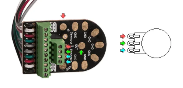
Refer to the diagram I post. All the red arrows, (pad labeled "In"), are the input to the pot.
All the green arrows, (center pad labeled "Out"), are the middle lug, or output of the pot.
All the cyan arrows, and every pad labeled "Gnd" are the same point.
The large terminal block is just that, with wires connected to it. You can can do anything you want with it. The colors are chosen to make it easy to wire two Duncan humbuckers, but they can be used for anything. They aren't connected to the pot.
I personally find the 4-term block odd. You aren't going to "quik-change" the pot. I'd solder the output of whatever switching you do to the "In" pad, the "Out" pad to the tip of the output jack, and the sleeve of the output jack to any "Gnd" pad. Your bridge ground would also solder to one of the "Gnd" pads.
After that, solder the flying leads however you want for what you're doing. For example, they could start from one end and just be N+/-, M+/-, B+/- . Just make sure you map what you're doing on paper so you can swap pups later. (That's what the Liberator is designed for.)
Hope this helps.