Bill Dennis
Active member
OK, here's the plan
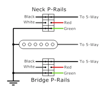
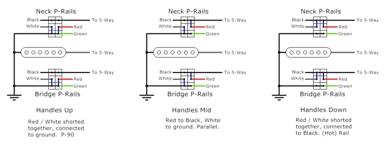
Bridge - P-Rail
middle - SSL-2 RWRP
Neck - P Rail
Going in a Player series Strat
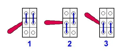
1) I want Parallel / P-90 / Rail options on the neck/bridge positions which I believe requires a DPDT on-on-on toggle for each to accomplish
2) I want SSL-2 to hum cancel paired with the P90 coil on the bridge and the rail coil on the neck so it needs to be RWRP
3) The P90 coils combined and the rail coils combined should naturally hum cancel. Using an on/off toggle to do the Gilmour mod to facilitate those combinations
4) 500k Volume pot to get the P90's snarling. Debating using a resister to let the SSL-2 see 250k
5) 5 way switch to select positions
I think that should work but I would like some other eyes on this. I have not used P Rails previously and want to make sure this is feasible and accurate before I order parts
Bridge - P-Rail
middle - SSL-2 RWRP
Neck - P Rail
Going in a Player series Strat
1) I want Parallel / P-90 / Rail options on the neck/bridge positions which I believe requires a DPDT on-on-on toggle for each to accomplish
2) I want SSL-2 to hum cancel paired with the P90 coil on the bridge and the rail coil on the neck so it needs to be RWRP
3) The P90 coils combined and the rail coils combined should naturally hum cancel. Using an on/off toggle to do the Gilmour mod to facilitate those combinations
4) 500k Volume pot to get the P90's snarling. Debating using a resister to let the SSL-2 see 250k
5) 5 way switch to select positions
I think that should work but I would like some other eyes on this. I have not used P Rails previously and want to make sure this is feasible and accurate before I order parts
Last edited:
")