Studiomaster Valve Leadmaster violated!!

Dreadneck

New member
Hi folks!

So I have some issues with my old but recently aquired Studiomaster amp.
It came to me in an absolute TERRIBLE shape to say the least!

If anyone out there could help me out here I would be very very grateful!

The questions I encountered while working on the amp was the following:

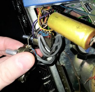
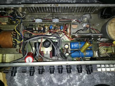
1. The yellow cap going from the output tube pcb to a pot(The one above the blue large caps), it connects to the output transformer. Should it be there?

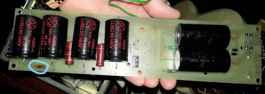
2. There is a resistor connected between the two first filter caps and it looks like someone added it. What does it do and should I remove it?

3. The filter caps that was in the amp had leaked, so I replaced them. But they has leaked out on the BIAS pot. I dont know if it has been affected. Should I swap it for a new one just to be shure?

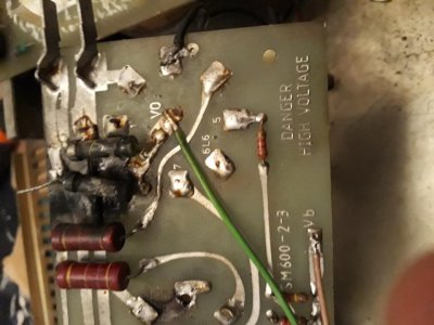
4. I read in a blogg about this amp where the guy writing swapped the diodes on the powerboard for new ones. The ones he chose didn't have the same name as the old ones. Now diodes I know very little about. Would it make any difference? And how do I know if they are working as they should?

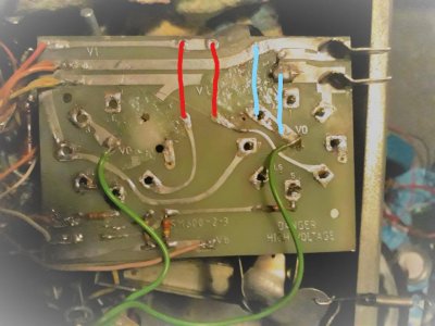
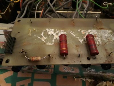
5. A big one! Two resistors (as can be seen in one of the pictures) was going from pin 8 and ground from the second of the 6L6 tubes. But as far as I know pin 8 is not used/just going to ground. Any way, they are burned beyond recognition. What was their function and what value could they have had?

6. The pcb holding the 6L6's was burned in the process apparently. How will it affect its function?

7. Does anyone have any idea what the bias on this amp should be set? I play my amps safely and not hot or cold.

Some clues to why this amp is wrecked: The obvious one, it is dirty and corroded as hell!, Some things was set up wrong; Output was set to 4ohms and it should be 8, the fuse on the back is completely gone missing, the transformer was set to 220V but here in Sweden we have 240V.
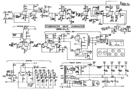
I included the schematic as well if anyone wanted to take a look at it.

Any help would be greatly appreciated and you will most definately recieve a mental hug and kiss!

Oh! And here's the link to a blogg concerning the amp: https://judyboxamp.blogspot.com/201...howComment=1541582333457#c7662408651823690666
20181104_204254.jpg

20181105_201848.jpg

studiomaster_valve_leadmaster_amp_sch.pdf_1.jpg
 
Re: Studiomaster Valve Leadmaster violated!!

OK , for starters , this is major damage.
attachment.php


5. A big one! Two resistors (as can be seen in one of the pictures) was going from pin 8 and ground from the second of the 6L6 tubes. But as far as I know pin 8 is not used/just going to ground. Any way, they are burned beyond recognition. What was their function and what value could they have had?

6. The pcb holding the 6L6's was burned in the process apparently. How will it affect its function?

Can you read schematics ? It answers these questions.[ I'm guessing you can't ]
1. The yellow cap going from the output tube pcb to a pot(The one above the blue large caps), it connects to the output transformer. Should it be there?

2. There is a resistor connected between the two first filter caps and it looks like someone added it. What does it do and should I remove it?

7. Does anyone have any idea what the bias on this amp should be set? I play my amps safely and not hot or cold.
It's on the schematic although the part values/voltages on that schematic are almost unreadable.

Do you have and know how to use a multi meter ?
 
Last edited:
Re: Studiomaster Valve Leadmaster violated!!

OK , for starters , this is major damage.
attachment.php


Yes it really is. I have started to repair it, I cut away the burned parts and build it upp again with epoxy. I will use copper to replace the damaged lines aswell.
It's starting to look good! I have made shure that there are no burned parts left.

Can you read schematics ? It answers these questions.[ I'm guessing you can't ]
Yes and no. Mostly no obviously.. I can read schematics to a point but when I have to search it for parts between stages it becomes difficult. Can you see these parts on the schematic?


It's on the schematic although the part values/voltages on that schematic are almost unreadable.

Sadly it is the best and only version of the schematic I could find.

Do you have and know how to use a multi meter ?

Yes I do and I know how to use it =)
My biggest issue is that I have no direct knowlege of why the components have a certain value and what they are suppposed to acomplish in their positions (in the builders point of view)
 
Re: Studiomaster Valve Leadmaster violated!!

Yes I do and I know how to use it =)
My biggest issue is that I have no direct knowlege of why the components have a certain value and what they are suppposed to acomplish in their positions (in the builders point of view)

Hi, I found a better schematic soI will get the Bias Values for you and check out your part concerns in the circuit.[ and post it for you ]

I have no direct knowlege of why the components have a certain value and what they are suppposed to acomplish in their positions
This is in the realm of electronic theory. You'd really need to study some of that and an amplifier design primer to understand that stuff. For the purposes of repair/ building amps you don't need to know it except in it's basic concepts.
 
Last edited:
Re: Studiomaster Valve Leadmaster violated!!

Here's where you can download a better quality schematic [ free ]
- https://elektrotanya.com/studiomaster_valve_leadmaster_amp_sch.pdf/download.html - [ it's slightly too big in data size to upload here.]

According to it , your Bias should be -91 Volts.
I can't see any cap connected between the output valves and the Output Transformer , in the circuit , nor any caps connected to that whole section. it may be best removed.[ what Mfd. value is on it ? I can't read it in your pic.]
Your two burnt out resistors are quite necessary. One is 2k2 Ohms and is on the input to the valve and the other is 470 Ohms and inputs a high voltage. [ I'm presuming to pin 8 [ Pins 1 & 6 are the only unused pins , 8 is used ]
- https://www.ampage.org/td/vtd6l6.html -
vt6l6.gif


For good measure , replace these on both valves. Also replacing your bias pot may be a good idea too.

There should be a resistor in parallel to both filter caps [ 180k Ohms ] Are you saying there is a third one between the two caps ?

Diodes are pretty basic components, Many will come with different part numbers but do the same thing. You can always put in diodes that are more capable, that can handle more power. The diodes in the Power Supply are used to rectify the power from AC to DC. They're easy to test.
 
Last edited:
Re: Studiomaster Valve Leadmaster violated!!

Thank you!!! You are a God send!

So the idle should be -91V if I get it correct? What would that translate to in amps? I've heard that everything between 30mA to 40mA is in the spot for 6L6's.


There should be a resistor in parallel to both filter caps [ 180k Ohms ] Are you saying there is a third one between the two caps ?


So maybe I was mixing up which caps it was. The burned spot in the circle is where the resistors was. They where sitting parallel in the same holes.

20181121_232920 (2)_LI.jpg


20181121_232954 (2)_LI.jpg

Also here is a picture of where the burnt resistors sat. The blue lines are the ones burned and the red lines is the larger ones that I just removed temporarily when repairing the board.

20181121_232843 (2)_LI.jpg

Here's that mystery cap again. It is 8uF 400/450V. You should just be able to see that it is connected to the ground of the master volume pot. The other end was connected to the big solder slab on the power tube board.

20181121_233022 (2).jpg


Now the next issue is figuring out WHY the resistors burned in the first place... I really hope that the transformers are in good shape. The amp was lighting up, which at least means that it gets power. But how much it gets is a totally different question.
When I got the amp it was corroded like hell and loads of sticky stuff was leaked all over. Some of it was from old caps but most of it must have come from eighter a spilled drink or moisture from outdoors/basement. I guess this could be a major factor.
When I think about it I believe that the former owner must have tried the amp in this state, the fuse was blown because of this, he then removed it out of ignorance and then killed the amp. This is what I hope at least.
 
Re: Studiomaster Valve Leadmaster violated!!

Firstly,. these pics of the board ? They're not of the board in your amp, are they ?
attachment.php


It makes a difference to what I've written below.

attachment.php

OK, the power board. Those four caps in the schematic are 33Mfd x3 and one 47Mfd.[ the last one, joined by the missing resistor ]
That resistor position should have a 15K Ohm. Those other resistors are 2 watt. The 15K is possibly a 1 watt.
Are those two other resistors a 10K Ohms and a 5.6K Ohms ?

That 8Mfd mystery cap doesn't exist in the circuit.
Here's that mystery cap again. It is 8uF 400/450V. You should just be able to see that it is connected to the ground of the master volume pot. The other end was connected to the big solder slab on the power tube board.
Probably just used as a ground point but not necessarily relevant to the Pot. I'd remove this cap.
I'm going to suggest that this amp has been modified [ or an attempt at modifying it. ] As I said , the schematic has three 33MFD caps on that board. Looking at the underside you can see plenty of resoldering at those caps.

What value [ Ohms ] are the two resistors you removed from the output board ? 470 Ohms ?

attachment.php


Where do the green wires go ? To the output transformer ? If so they're connected to the wrong terminals. Pin 8 should go to ground. The transformer wires should be on pin 3 of each valve.
Once again I'm wondering if some one tried to modify it to run different valves.
The soldering in the bottom left corner is very messy.
Also I can't figure what the burnt out resistors are, they don't seem to be in the circuit. They may well have been part of a failed mod.
Where do the two pins at the edge go to ? They look like the heater voltage feeds. The bottom one is connected to pin 2 on one . the trace between that and pin 2 on the other valve appears to have been cut and bits removed. More signs of modification.
 
Last edited:
Re: Studiomaster Valve Leadmaster violated!!

So the idle should be -91V if I get it correct? What would that translate to in amps? I've heard that everything between 30mA to 40mA is in the spot for 6L6's.
Don't know actually. I'd just set it using a multi meter to read the voltage. Either way, you've a fair bit of work to do before you get to this.

This amp is going to take a bit of work to get it going again. Were there output valves with it ?
 
Re: Studiomaster Valve Leadmaster violated!!

Firstly,. these pics of the board ? They're not of the board in your amp, are they ?
attachment.php


Yes they are of the board in my amp, before I removed the old caps.

It makes a difference to what I've written below.

attachment.php

OK, the power board. Those four caps in the schematic are 33Mfd x3 and one 47Mfd.[ the last one, joined by the missing resistor ]
That resistor position should have a 15K Ohm. Those other resistors are 2 watt. The 15K is possibly a 1 watt.
Are those two other resistors a 10K Ohms and a 5.6K Ohms ?

Yes they are 10K and 5,6K.

That 8Mfd mystery cap doesn't exist in the circuit.
Probably just used as a ground point but not necessarily relevant to the Pot. I'd remove this cap.
I'm going to suggest that this amp has been modified [ or an attempt at modifying it. ] As I said , the schematic has three 33MFD caps on that board. Looking at the underside you can see plenty of resoldering at those caps.

I believe that as well, many of the solder spots are poorly made. I really think someone has tried to mod it, but it feels like they just went nuts with the solder iron.

What value [ Ohms ] are the two resistors you removed from the output board ? 470 Ohms ?

Yes they are 470 ohms.

attachment.php


Where do the green wires go ? To the output transformer ? If so they're connected to the wrong terminals. Pin 8 should go to ground. The transformer wires should be on pin 3 of each valve.
Once again I'm wondering if some one tried to modify it to run different valves.
The soldering in the bottom left corner is very messy.
Also I can't figure what the burnt out resistors are, they don't seem to be in the circuit. They may well have been part of a failed mod.
Where do the two pins at the edge go to ? They look like the heater voltage feeds. The bottom one is connected to pin 2 on one . the trace between that and pin 2 on the other valve appears to have been cut and bits removed. More signs of modification.


The green wires goes to chassi ground, so I believe they are correct. No the burnt resistors feels wrong. To me it looks like they where creating a loop of sorts that should'nt exist.
The two pins goes to the power transformer, so heaters seems probable. Yes i guess it has been damaged and removed in the heat of experiment. My plan is to cut out new pieces in copper tape and solder it to the good pieces of trace.

I found this picture I took of the resistors that was placed with the caps. The upper one that we can see are a 22 ohm.

20181108_132801.jpg

Yes it will take lots of work to get this old amp up and running, it is a great project for slow weekends ;)
 
Re: Studiomaster Valve Leadmaster violated!!

I just saw that some of my answers ended up inside the quote square. Sorry for that! Hope you can see them.
 
Re: Studiomaster Valve Leadmaster violated!!

I just saw that some of my answers ended up inside the quote square. Sorry for that! Hope you can see them.

Yes, got it.
The green wires goes to chassi ground, so I believe they are correct.
sounds right.

That 22 Ohm resistor looks like part of "The Experiment ". As I pointed out before it should be 15 K Ohms.

Yes it will take lots of work to get this old amp up and running, it is a great project for slow weekends ;)

I'm glad you realize this and have the enthusiasm to tackle it.

Sorry to ask this again. How well can you read schematics ? Being able to read them just basically would be a big help to you.
 
Re: Studiomaster Valve Leadmaster violated!!

Yes, got it.
sounds right.

That 22 Ohm resistor looks like part of "The Experiment ". As I pointed out before it should be 15 K Ohms.


I'm glad you realize this and have the enthusiasm to tackle it.

Sorry to ask this again. How well can you read schematics ? Being able to read them just basically would be a big help to you.

Yes I definitely realize that and I got it for almost nothing with the intention to fix it and see what it can do. Allthough it turned out to be a more difficult task than I expected.
Funnily enough it makes the amp more fun when I have to fix it first, same with guitars actually =)

Ok, so then I could just cut the resistor away. I always felt a little odd.

No worries =) I can read schematics ok, if I give it time and really sit down with it looking inside the amp at the same time, I can figure most of it. I know the symbols and have a basic understanding of how they are drawn. The biggest issues I have is when someone add new parts or change things around. That throws me off!
 
Re: Studiomaster Valve Leadmaster violated!!

[/QUOTE]Ok, so then I could just cut the resistor away[/QUOTE] Just unsolder it.

You ought to test your output transformer.
 
Last edited:
Re: Studiomaster Valve Leadmaster violated!!

You ought to test your output transformer.[/QUOTE]


Is there a way to test it without a Variac?
 
Re: Studiomaster Valve Leadmaster violated!!

You ought to test your output transformer.


Is there a way to test it without a Variac?

Yes, use a multimeter. Set it to x 1K or similar setting and put your probes on the primary coil connections [ connected to pin 3 of your 6l6's ] It should read at least 1.5K or more, maybe up to 6 > 10 K. If it is lower Ohms or really low ohms it's probably shorted out. If it's no Ohms , it's burnt out.

You could do the same for the secondary coil [ speaker output ] with the multi meter set to x 1 Ohm range. I'd expect 6-8 Ohm reading.
 
Re: Studiomaster Valve Leadmaster violated!!

Yes, use a multimeter. Set it to x 1K or similar setting and put your probes on the primary coil connections [ connected to pin 3 of your 6l6's ] It should read at least 1.5K or more, maybe up to 6 > 10 K. If it is lower Ohms or really low ohms it's probably shorted out. If it's no Ohms , it's burnt out.

You could do the same for the secondary coil [ speaker output ] with the multi meter set to x 1 Ohm range. I'd expect 6-8 Ohm reading.

I see, thank you! I will test it later today if time is on my side. Perhaps I should test the others as well. There are four transformers. I guess it's power, output, reverb and choke?
 
Re: Studiomaster Valve Leadmaster violated!!

I see, thank you! I will test it later today if time is on my side. Perhaps I should test the others as well. There are four transformers. I guess it's power, output, reverb and choke?

So I meashured the resistance.
I got 92ohms across primary and .7 across each of the secondary.
Worth noting is that I didn't have any current running through the OT. So the readings come from the OT completely disconnected.

What do you think?
 
Re: Studiomaster Valve Leadmaster violated!!

So I meashured the resistance.
I got 92ohms across primary and .7 across each of the secondary.
Worth noting is that I didn't have any current running through the OT. So the readings come from the OT completely disconnected.[ best way to test :bigok: ]

What do you think?

this
Yes, use a multimeter. Set it to x 1K or similar setting and put your probes on the primary coil connections [ connected to pin 3 of your 6l6's ] It should read at least 1.5K or more, maybe up to 6 > 10 K. If it is lower Ohms or really low ohms it's probably shorted out. If it's no Ohms , it's burnt out.

You could do the same for the secondary coil [ speaker output ] with the multi meter set to x 1 Ohm range. I'd expect 6-8 Ohm reading.

From your figures I'd say the OT is shot [ the secondary is an 8 Ohm out with a 4 Ohm centre tap - should read about 6 Ohms and 2>3 Ohms on the centre tap ]
The primary is centre tapped too.

What ever took out those burnt out resistors probably took out the OT too and an output valve or two. It looks like it's had a pretty good major malfunction.

is there any identifying marks / numbers /brand - model on the OT ?
 
Re: Studiomaster Valve Leadmaster violated!!

this


From your figures I'd say the OT is shot [ the secondary is an 8 Ohm out with a 4 Ohm centre tap - should read about 6 Ohms and 2>3 Ohms on the centre tap ]
The primary is centre tapped too.

What ever took out those burnt out resistors probably took out the OT too and an output valve or two. It looks like it's had a pretty good major malfunction.

is there any identifying marks / numbers /brand - model on the OT ?

No there is no markings at all. The schematics does'nt say anything about it eighter.
Could I buy one that is made for two 6l6 tubes and 4 to 8 ohm?
Or is it worth it to rewind it myself? The laminates looks good and there is no rust on the sides.

I'm getting more and more condused about what may have caused this havoc..
 
Re: Studiomaster Valve Leadmaster violated!!

No there is no markings at all. The schematics does'nt say anything about it eighter.
Could I buy one that is made for two 6l6 tubes and 4 to 8 ohm?
Or is it worth it to rewind it myself? The laminates looks good and there is no rust on the sides.

I'm getting more and more condused about what may have caused this havoc..

I'll see if I can find more info about the OT. Were there output valves with it ? and what sort of valves ? The original circuit runs 6L6's. As I said before, it looks like it was modded to run different valves. It may have been a disaster from the beginning...

There's probably a Hammond Transformer that will do the job but getting a clearer picture of what's damaged and needs fixing / replacing first would be expedient.
 
Last edited:
Back
Top