Studiomaster Valve Leadmaster violated!!

Re: Studiomaster Valve Leadmaster violated!!

I'll see if I can find more info about the OT. Were there output valves with it ? and what sort of valves ? The original circuit runs 6L6's. As I said before, it looks like it was modded to run different valves. It may have been a disaster from the beginning...

There's probably a Hammond Transformer that will do the job but getting a clearer picture of what's damaged and needs fixing / replacing first would be expedient.

It was 6l6s in it when I got it. Visualy they seemed fine but I did not dare to turn the amp on to try them.

I just tested the power transformer and it seemed to work as it should. I got all the voltages that it was supposed to put out.
So I guess that we could rule that out.
 
Re: Studiomaster Valve Leadmaster violated!!

Ok, so I just put 6.3VAC into the secondary and got 140VAC on the primary.
That seems to be what one would expect from a working OT right?
Or is it just telling me something else?
 
Re: Studiomaster Valve Leadmaster violated!!

Ok, so I just put 6.3VAC into the secondary and got 140VAC on the primary.
That seems to be what one would expect from a working OT right?
Or is it just telling me something else?

It appears to be fine , just not a way I have tested an OT. Your readings [ Ohms ] from the coils don't suggest that though.
 
Last edited:
Re: Studiomaster Valve Leadmaster violated!!

It appears to be fine , just not a way I have tested an OT. Your readings [ Ohms ] from the coils don't suggest that though.

That's what puzzels me aswell.
I keep thinking that I have made a misstake somewhere.
I took ohm readings between the primary leads and between the secondary taps to commons. That's right isn't it?
What I would like to find out is what voltages is supposed to run through the OT when the amp is up and running. Them I could try to put that into it and see what readings I get.
 
Re: Studiomaster Valve Leadmaster violated!!

That's what puzzels me aswell.
I keep thinking that I have made a misstake somewhere.
I took ohm readings between the primary leads and between the secondary taps to commons. That's right isn't it?
What I would like to find out is what voltages is supposed to run through the OT when the amp is up and running. Them I could try to put that into it and see what readings I get.

It's on the schematic at the Power Supply section - HT = 485 Volts DC. - which goes to the centre tap on the primary side of the OT. A DC voltage won't pass through the transformer, only AC [ sound ] will pass through it. I don't think feeding it a high AC voltage is going to do it any good or display any relevant results.
 
Last edited:
Re: Studiomaster Valve Leadmaster violated!!

It's on the schematic at the Power Supply section - HT = 485 Volts DC. - which goes to the centre tap on the primary side of the OT. A DC voltage won't pass through the transformer, only AC [ sound ] will pass through it. I don't think feeding it a high AC voltage is going to do it any good or display any relevant results.

I've been looking into the impedances further.
I fed 67VAC into the primary and got 2.5VAC on the 4ohm and 1.6VAC on 8ohm lead.
So after some calculations the primary impedance on 4 ohm is 5745 ohm
and on 8 ohm it is 7013 ohms.
Should'nt these numbers be more concistent?

The turns ratio seems to be 1:31 and 1:23.

I also read the impedance between primary again and it is 92.8 ohm while to center tap one lead is 49.8 ohms and the other is 42.2 ohms. So there is inconcistancies here, not very large but still.

The readings between the secondarys was 0.5 and 0.35 which seems correct according to the relationship they should have if you take 0.5 times the square root of 2.

I have looked for resistance between both primary and laminates and found nothing, which is good. There is no resistance what so ever between primary and secondary, it doesn't give a reading.

What do these numbers tell you? To me the main questionmark is the inconcistancies between the primary impedances.
 
Re: Studiomaster Valve Leadmaster violated!!

I can see on a chart now that 6L6's works in both 5000 and 7000 ohms. So could this be why the readings differ so much?
 
Re: Studiomaster Valve Leadmaster violated!!

Quite possibly yes but I was going to try and find out what exactly is in the amp, I haven't got to it yet.

I'll see if I can find more info about the OT.

There's probably a Hammond Transformer that will do the job but getting a clearer picture of what's damaged and needs fixing / replacing first would be expedient.
 
Re: Studiomaster Valve Leadmaster violated!!

Part Number

[TD="width: 86, bgcolor: #cccccc"]
Audio Watts (RMS)
[/TD]
[TD="width: 101, bgcolor: #cccccc"]
Primary
Impedance
(Ohms)
[/TD]
[TD="width: 192, bgcolor: #cccccc"]
Operation
[/TD]
[TD="width: 318, bgcolor: #cccccc"]
Suggested Tube Types
[/TD]

[TD="width: 86"] [SIZE=+1]1608[/SIZE] [/TD]
[TD="width: 86"]
10​
[/TD]
[TD="width: 101"]
8,000 ct​
[/TD]
[TD="width: 192"]Push-Pull (2 Tubes)[/TD]
[TD="width: 318"]
6AQ5, 6V6, 6BQ5, EL84, SV83​
[/TD]

[TD="width: 86"] [SIZE=+1]1609[/SIZE] [/TD]
[TD="width: 86"]
10​
[/TD]
[TD="width: 101"]
10,000 ct​
[/TD]
[TD="width: 192"]Push-Pull (2 Tubes)[/TD]
[TD="width: 318"]
6AQ5, 6V6, 6BQ5, EL84, SV83​
[/TD]

[TD="width: 86"] [SIZE=+1]1615[/SIZE] [/TD]
[TD="width: 86"]
15​
[/TD]
[TD="width: 101"]
5,000 ct​
[/TD]
[TD="width: 192"]Push-Pull (2 Tubes)[/TD]
[TD="width: 318"]
2A3, 6A3, 6AQ5, 6B4G, 6L6, 6V6​
[/TD]

[TD="width: 86"] [SIZE=+1]1620[/SIZE] [/TD]
[TD="width: 86"]
20​
[/TD]
[TD="width: 101"]
6,600 ct​
[/TD]
[TD="width: 192"]Push-Pull (2 Tubes)[/TD]
[TD="width: 318"]
6AQ5, 6L6, 6V6​
[/TD]

[TD="width: 86"] [SIZE=+1]1650F[/SIZE] [/TD]
[TD="width: 86"]
25​
[/TD]
[TD="width: 101"]
7,600 ct​
[/TD]
[TD="width: 192"]Push-Pull (2 Tubes)[/TD]
[TD="width: 318"]
6L6GC, 6V6, 807, 5881, EL34​
[/TD]

[TD="width: 86"] [SIZE=+1]1645[/SIZE] [/TD]
[TD="width: 86"]
30​
[/TD]
[TD="width: 101"]
5,000 ct​
[/TD]
[TD="width: 192"]Push-Pull (2 Tubes)[/TD]
[TD="width: 318"]
6L6GC, 6V6, 807, 5881, EL34​
[/TD]

[TD="width: 86"] [SIZE=+1]1650H[/SIZE] [/TD]
[TD="width: 86"]
40​
[/TD]
[TD="width: 101"]
6,600 ct​
[/TD]
[TD="width: 192"]Push-Pull (2 Tubes)[/TD]
[TD="width: 318"]
6L6GC, 807, 5881, EL34​
[/TD]

[TD="width: 86"] [SIZE=+1]1650K[/SIZE] [/TD]
[TD="width: 86"]
50​
[/TD]
[TD="width: 101"]
3,400 ct​
[/TD]
[TD="width: 192"]Push-Pull Par. (4 Tubes)[/TD]
[TD="width: 318"]
6L6GC, 807, 5881, EL34, 6146B, 6550B​
[/TD]

[TD="width: 86"] [SIZE=+1]1650N[/SIZE] [/TD]
[TD="width: 86"]
60​
[/TD]
[TD="width: 101"]
4,300 ct​
[/TD]
[TD="width: 192"]Push-Pull Par. (2 or 4 Tubes)[/TD]
[TD="width: 318"]
6L6GC, 807, 5881, EL34, 6146B, 6550B, KT88​
[/TD]

[TD="width: 86"] [SIZE=+1]1650P[/SIZE] [/TD]
[TD="width: 86"]
60​
[/TD]
[TD="width: 101"]
6,600 ct​
[/TD]
[TD="width: 192"]Push-Pull (2 Tubes)[/TD]
[TD="width: 318"]
6L6GC, 807, 5881, EL34, 6146B, 6550B, KT88​
[/TD]

[TD="width: 86"] [SIZE=+1]1650R[/SIZE] [/TD]
[TD="width: 86"]
100​
[/TD]
[TD="width: 101"]
5,000 ct​
[/TD]
[TD="width: 192"]Push-Pull Par. (2 or 4 Tubes)[/TD]
[TD="width: 318"]
807, 5881, EL34, 6146B, 6550B, KT88​
[/TD]

[TD="width: 86"] [SIZE=+1]1650T[/SIZE] [/TD]
[TD="width: 86"]
120​
[/TD]
[TD="width: 101"]
1,900 ct​
[/TD]
[TD="width: 192"]Push-Pull Par. (4 or 6 Tubes)[/TD]
[TD="width: 318"]
6L6GC, 5881, EL34, 6550B, KT88​
[/TD]

[TD="width: 86"] [SIZE=+1]1650W[/SIZE] [/TD]
[TD="width: 86"]
280​
[/TD]
[TD="width: 101"]
1,900 ct​
[/TD]
[TD="width: 192"]Push-Pull Par. (6 or 8 Tubes)[/TD]
[TD="width: 318"]
6L6GC, 5881, EL34, 6550B, KT88


[/TD]


I'd go for the 1750M or a 1650N [ or 1650P ]. The amp is 60 watts.
 
Re: Studiomaster Valve Leadmaster violated!!

I'd go for the 1750M or a 1650N [ or 1650P ]. The amp is 60 watts.
Awesome! I ordered the 1750M. Thank you so much for looking it up!

Btw, the choke and the reverb transformer, do you have any clue what specs they have/should have? Is there a way to check them?

Also I made a mistake when I ordered caps.. I bought two 220uF 300V but according to the schematics they should be 200uF 350V. I'm not so much concerned with the extra 20uF,
but I don't think it is a good idea to put 300V caps where there should be 350.
So I just have to order new ones again.
 
Re: Studiomaster Valve Leadmaster violated!!

Awesome! I ordered the 1750M. Thank you so much for looking it up!

Btw, the choke and the reverb transformer, do you have any clue what specs they have/should have? Is there a way to check them?

Also I made a mistake when I ordered caps.. I bought two 220uF 300V but according to the schematics they should be 200uF 350V. I'm not so much concerned with the extra 20uF,
but I don't think it is a good idea to put 300V caps where there should be 350.
So I just have to order new ones again.


Any markings/model numbers on either of those transformers ?
You should be able to test the with a multi meter across each coil. The choke would probably read low Ohms, to what appears like a short. As long as it isn't open circuit [ no Ohms ] it should be fine.
The Reverb transformer could be anywhere from a couple of hundred Ohms to a few K Ohms. One side will differ to the other.
Testing them diconnected from the circuit will give you the most accurate readings.

Yes , voltage under-rated caps is not a good idea as any voltage peaks over the rated maximum can cause them to die.
The way those two are connected in this amp makes this not as big a concern. They're in series which gives you a max of 700V capacity. The HT voltage there is 485 V at the positive of those two, giving you over 200 Volts headroom. The 300 volt caps would lower that by 100 Volts and maybe put it into an area that won't handle voltage peaks, but it probably would be ok.
 
Re: Studiomaster Valve Leadmaster violated!!

I will check it!

I actually dumb as I am tried to start the amp today with the existing OT and the 300V caps etc.. But everything was hooked up and connected.
The result was that the ground wire from the power circuit board burned of. I thought that it could just be that the wire was poorly soldered, so I resoldered it. And what happened was that
thin smoke and sparkling noises came from the 300V caps.
Offcourse I turned it of immediately, but it left me wondering what the hell happened.
I didn't have any tubes in it, neighter preamp tubes nor power tubes, but I didn't think that would neccecarily cause a problem when just testing to start it.
So now I guess it is back to looking for shorts. The issue seems to appear in the power section though.
 
Re: Studiomaster Valve Leadmaster violated!!

I will check it!

I actually dumb as I am tried to start the amp today with the existing OT and the 300V caps etc.. But everything was hooked up and connected.
The result was that the ground wire from the power circuit board burned of. I thought that it could just be that the wire was poorly soldered, so I resoldered it. And what happened was that
thin smoke and sparkling noises came from the 300V caps.
Offcourse I turned it of immediately, but it left me wondering what the hell happened.
I didn't have any tubes in it, neither preamp tubes nor power tubes, but I didn't think that would neccecarily cause a problem when just testing to start it.
So now I guess it is back to looking for shorts. The issue seems to appear in the power section though.
No, it shouldn't


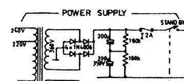
The thing to do would be check the diodes prior to the caps, the IN4006's. Also if you try firing it up again, do it without the standby on and the fuse removed. [ did you try it this way before ? ]If all is ok just that first part of the PS would fire up and you should be able to read the HT of 485 DC volts on the cap side of the fuse holder.
What sort of multi meter do you have ? Does it have a Diode testing facility on it ?
Check that you have the polarity of the caps right. If you get them backwards they will explode.
 
Last edited:
Re: Studiomaster Valve Leadmaster violated!!

It appears to be fine , just not a way I have tested an OT. Your readings [ Ohms ] from the coils don't suggest that though.

I revisited testing OT's . Your AC test is in the ball park if not a bit high on the output. The ohm reading is also in an area that they will read when testing with a multimeter. The DCR reading is quite different to the Impedance of the OT. [ my mistake I was making ]
 
Re: Studiomaster Valve Leadmaster violated!!

I revisited testing OT's . Your AC test is in the ball park if not a bit high on the output. The ohm reading is also in an area that they will read when testing with a multimeter. The DCR reading is quite different to the Impedance of the OT. [ my mistake I was making ]

I see, so what does this mean? Is the OT functioning as it should?
What do you think the problem with the caps come from in that case? I looked at the diodes and four of them are 1N5399 and four are 1N4007. So none of them are 1N4006. Hur would that make a differense?
 
Re: Studiomaster Valve Leadmaster violated!!

I see, so what does this mean? Is the OT functioning as it should?
What do you think the problem with the caps come from in that case? I looked at the diodes and four of them are 1N5399 and four are 1N4007. So none of them are 1N4006. Hur would that make a differenCe?

I think you said they'd been replaced.
The differences, not a lot. The 4007's have a slightly higher voltage capacity. The 1N5399 are pretty much the same voltage wise and a slightly higher ampage capacity [ 1.5 Amp ][ 4006 & 4007 = 1 Amp ca[pacity ]
Anyway , did you test them ?

I see, so what does this mean? Is the OT functioning as it should?
What do you think the problem with the caps come from in that case?
Yes , it seems it maybe ok.

Until you've tested the diodes, I'm not sure.


Attachments

  • ValvemasterPS-1.jpg
    ValvemasterPS-1.jpg
    16.3 KB · Views: 0
Last edited:
Re: Studiomaster Valve Leadmaster violated!!

I think you said they'd been replaced.
The differences, not a lot. The 4007's have a slightly higher voltage capacity. The 1N5399 are pretty much the same voltage wise and a slightly higher ampage capacity [ 1.5 Amp ][ 4006 & 4007 = 1 Amp ca[pacity ]
Anyway , did you test them ?

Yes , it seems it maybe ok.

Until you've tested the diodes, I'm not sure.


Yes I did change them =) I just got it mixed up. I installed them in the direction that the originals were facing, the polarity is the same.
I've tested them and they check out fine. But what gets me confused is that if I look at the underside of the pcb it looks like the diodes is supposed to face the other direction. So I tried switching them. What happened then was....... nothing. Except that the lightbulb I got between the amp and wall was lit up very bright. So I turned the amp off quick!
So right now I'm a bit confused on how to place them. I've seen pictures where the diodes is facing the same direction as I first had. But that seems wrong when you look at the pplus signs under the pcb....

I also replaced the resistors that goes with the filtercaps and the one next to the bias pot.
After that there were no more crackling noises from the caps but as far as I know they could be dead now.. I don't think that it is a good sign when caps is snapping and popping,
even though the amp was on for a few seconds.
 
Re: Studiomaster Valve Leadmaster violated!!

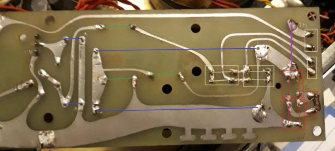
Diodes.jpg

So here I took a photo of the underside.

Green lines = Resistors
Blue lines = Caps
Purple line = Fuse
The colors represents the diodes and the color of the wires that comes from the PT.

The current goes from positive to negative right? I just don't get my head around it here. This is where my lacking skills in electricity shows....
 
Back
Top