Re: Wiring diagram help
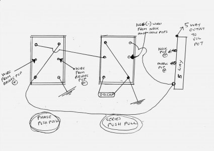
Awesome Brandenburg. I do have a couple questions. Is this using the 50s gibson style wiring that allows for better treble control upon volume rolloff? There are several jumpers on the switch, and some splice off to a pot or pickup. Am I able to connect in at any point in that chain, or should it be specific to the picture, i.e. the blue wire on the first tone connects into the switch jumpers at #4 or the pink route going into the volume. Also, do you happen to have a chart or a quick walkthrough for following the position/DPDT options? Thanks again!
no 50's wiring.. id actually have to look what that it.. Im assuming a treble bleed circuit?
Maby i should give you my color code description:
For pickups I followed Seymour Duncan color codes by default unless requested to do otherwise
HUMBUCKERS
-------------------
NORTH start(+):BLACK
NORTH finish(-):LT Grey
SOUTH finish(+):RED
SOUTH start(-):GREEN
SINGLE COILS
---------------
Start(+):RED
finish:thin black lines
--My color codes--
hot/signal:Magenta
Grounds:thin black
Tone/caps:Blue
nodes or solder points: dark grey
dont try to overthink it here.. If you don't understand whats going on with the wiring.. don't try to be clever here or things might not go according to plan.
"warning".. Its not advisable to change stuff around unless you understand what I had done, why I had done it that way, and the theory behind it. FOR SURE.. there are several wiring solutions to each problem alot of time.. not all the time but most the time there is.. Just a friendly warning but you can do as you see fit.... Its best just to get it working then tweak it a bit..or get one switch working first.. then add another and so forth.. easier to troubleshoot when you do it like this .. especially when you are new at this.. I speak from experience here
generally.. if a wire goes off the switch to the pot.. its better if its done that way. Not always but IMO.. its easier and keeps wire length to a minimum which helps keep the noise from seeping into the circuit.. longer wire increases the possibility of noise IMO.. Now some you can just wire where ever as long as they are connected in the "chain" (i.e electronically connected) but there some cases where it has to be done a certain way...
best thing to do is just trace the wires with you fingers or print out a few copies and start drawing arrows with a pen.I use legal sized paper in this program BTW. just find you an explanation of how a DPDT or super switch works..
here is a quick explanation on the push/pull DPDT pot.. the 2 middle lugs are "commons" and depending on if the pot is pulled or pushed.. there will be an electronic connected to either the top or bottom lugs.. think of a DPDT switch like having 2 SPDT switchs that are linked together but are electronically isolated.. i.e. You pull the pot.. the commons and both bottom lugs are active at the same time but must treat them as individual switches unless you add a jumper so that current can pass through one side to the other.easiest way to remember it for me is that down(push) or default are the top lugs of the switch and when you pull the pot (up), the bottom lugs are active.i.e ones closest to the pot
Not sure about drawing you a diagram/chart about what every switch does as I thought I had already done that right above my name. Maby I can give you a graphical walk through wire trace but that will take time to do and not exactly sure how I want to do that.. several different ways but it might be time consuming..Ill try to work on it tonight.. try is the operative word though..Let me think on it
This drawing should meet your requirements and work as advertised.. unless one of my peers comes in and tells me there is an issue or something doesnt look right.. sometimes it happens.. sometimes it doesn't.. if it does and its proven that the drawing is in error.. Ill make a revision
")


")