You are using an out of date browser. It may not display this or other websites correctly.
You should upgrade or use an alternative browser.
You should upgrade or use an alternative browser.
Wiring humbucker to switch from parallel to split.
- Thread starter Benjy_26
- Start date
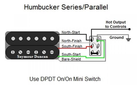
Its same as a series/parallel wiring, like this
 but you add a jumper from one of the bottom two terminals to either one of the top two terminals depending on which coil you want to split to: jumper to the terminal with the hot (black) lead to split to the south (screw) coil. Jumper to the terminal with the ground (green and bare) lead for the north (slug) coil.
 but you add a jumper from one of the bottom two terminals to either one of the top two terminals depending on which coil you want to split to: jumper to the terminal with the hot (black) lead to split to the south (screw) coil. Jumper to the terminal with the ground (green and bare) lead for the north (slug) coil.
Benjy_26
25's Nemesis
Its same as a series/parallel wiring, like this
but you add a jumper from one of the bottom two terminals to either one of the top two terminals depending on which coil you want to split to: jumper to the terminal with the hot (black) lead to split to the south (screw) coil. Jumper to the terminal with the ground (green and bare) lead for the north (slug) coil.
Thanks!
ThreeChordWonder
New member
The first way to do it is like this:
The third way is to ground both ends of the switch-off-able coil.
The switch-off-able coils ground wire goes directly to ground. It's hot wire goes to the common lug on the push-pull. In push it connects to the hot from the permanently on coil then to the volume ot or switch. In pull it goes to ground.
- Solder the white, green and bare wires directly to ground.
- Decide which pickup coil you want to be permanently on, regardless of the push-pull setting. It will either be the black for the north / slug coil or the red for the south / screw coil
- Solder that wire to the "push" lug on the push-pull and then on to the selector switch or volume pot.
- Wire the other "hot" (red or black) to the common lug on the push pull.
- In push, both "hots" (red and black) will connect to the volume pot or selector switch. In pull, only the permanently on hot will be connected.
The third way is to ground both ends of the switch-off-able coil.
The switch-off-able coils ground wire goes directly to ground. It's hot wire goes to the common lug on the push-pull. In push it connects to the hot from the permanently on coil then to the volume ot or switch. In pull it goes to ground.
Benjy_26
25's Nemesis
The first way to do it is like this:The second way to do it is if you want to isolate both ends of the switch-off-able coil in the pull position. In that case solder its ground (green or white) to the other common lug on the push-pull and ground the corresponding push lug. So in push both the hot and ground wires for the switch-off-able coil are connected, in pull they are both isolated.
- Solder the white, green and bare wires directly to ground.
- Decide which pickup coil you want to be permanently on, regardless of the push-pull setting. It will either be the black for the north / slug coil or the red for the south / screw coil
- Solder that wire to the "push" lug on the push-pull and then on to the selector switch or volume pot.
- Wire the other "hot" (red or black) to the common lug on the push pull.
- In push, both "hots" (red and black) will connect to the volume pot or selector switch. In pull, only the permanently on hot will be connected.
The third way is to ground both ends of the switch-off-able coil.
The switch-off-able coils ground wire goes directly to ground. It's hot wire goes to the common lug on the push-pull. In push it connects to the hot from the permanently on coil then to the volume ot or switch. In pull it goes to ground.
Thanks! I'll play around with the wiring and see which coil sounds the best.
The diagram by hwiho2002 did not answer your question. Don't use that.
The instructions by TCW are accurate. Either of the 3 solutions he gave will work. Just use whichever one is easiest for you to wire.
How did it not answer the question? By adding a jumper to one of the top terminals you'd be sending the red+white leads to either the hot or ground, which is how you split to either coils.
ThreeChordWonder
New member
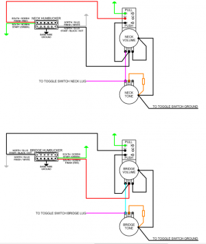
I think this will work.
As usual, drawn in Seymour Duncan colors for a Seymour Duncan forum.
I've arranged it so that the neck pickup slug (north) coil is permanently on, and the coil split deactivates the screw (south) coil. For the bridge, it's the opposite. The south (screw) coil stays permanently on, and the slug (north) coil gets deactivated. This should mean in the middle position, with both coils split, you get hum canceling. If you want the splits outher ways I'm sure you can see how it would be done. It's also possible to arrange both coil splits to be done on one single push pull.
Just a final reminder, DO NOT ground the volume pots to each other. I have no idea why, but if you do so you won't get independent volumes.

I think this will work.
As usual, drawn in Seymour Duncan colors for a Seymour Duncan forum.
I've arranged it so that the neck pickup slug (north) coil is permanently on, and the coil split deactivates the screw (south) coil. For the bridge, it's the opposite. The south (screw) coil stays permanently on, and the slug (north) coil gets deactivated. This should mean in the middle position, with both coils split, you get hum canceling. If you want the splits outher ways I'm sure you can see how it would be done. It's also possible to arrange both coil splits to be done on one single push pull.
Just a final reminder, DO NOT ground the volume pots to each other. I have no idea why, but if you do so you won't get independent volumes.
That's actually less convoluted than what I suggested. I'd go with that.
How did it not answer the question? By adding a jumper to one of the top terminals you'd be sending the red+white leads to either the hot or ground, which is how you split to either coils.
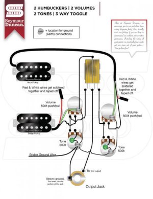
The diagram was for series/parallel. It did not show just parallel/split as you asked. Sure, that diagram can be modified (as he explained below the diagram), but without knowing your wiring knowledge and experience it's best to just give you a direct answer/diagram to your question without muckying it up (and in fact, the very fact that you asked that question the way you did would indicate that you don't have much wiring expertise. That's not critical of you, just an observation...we ALL had no knowledge of this stuff at one point. We learn and we help others to also learn). TCW gave you that diagram...very clear and concise. Just ignore his statement about grounding the volume pots (because the vol pots are grounded to their tone pots, both tone pots are grounded to the toggle switch ground, therefore the volume pots ARE grounded to each other. It just took a few more inches of wire to get there).
ThreeChordWonder
New member
I stand by what I said. Do not ground the volume pots to each other. If you do, you won't get jndependent volumes. I made that mistake and had to correct it.
See also:
https://www.google.com/amp/s/www.premierguitar.com/amp/les-paul-independent-volume-wiring-2651070921

See also:
https://www.google.com/amp/s/www.premierguitar.com/amp/les-paul-independent-volume-wiring-2651070921

The diagram was for series/parallel. It did not show just parallel/split as you asked. Sure, that diagram can be modified (as he explained below the diagram), but without knowing your wiring knowledge and experience it's best to just give you a direct answer/diagram to your question without muckying it up (and in fact, the very fact that you asked that question the way you did would indicate that you don't have much wiring expertise. That's not critical of you, just an observation...we ALL had no knowledge of this stuff at one point. We learn and we help others to also learn). TCW gave you that diagram...very clear and concise. Just ignore his statement about grounding the volume pots (because the vol pots are grounded to their tone pots, both tone pots are grounded to the toggle switch ground, therefore the volume pots ARE grounded to each other. It just took a few more inches of wire to get there).
You quoted my message, but your wording makes it seem like you're talking to the original poster. Are you talking to me or the op?
Regardless, like I said in my original reply to the op, I explained that adding a jumper to the diagram I provided would get what they want. If the op didn't understand that they would've asked for clarification.
To just flat out say I'm wrong with no elaboration, and to undermine the op's understanding of wiring, and the fact that your contribution to this thread is to just evaluate and approve/disapprove others replies makes you appear very conceited, and as you say "abrasive."
You quoted my message, but your wording makes it seem like you're talking to the original poster. Are you talking to me or the op?
Yes, I got a little confused about who I was talking to. Sorry.
Regardless, like I said in my original reply to the op, I explained that adding a jumper to the diagram I provided would get what they want. If the op didn't understand that they would've asked for clarification.
To just flat out say I'm wrong with no elaboration, and to undermine the op's understanding of wiring, and the fact that your contribution to this thread is to just evaluate and approve/disapprove others replies makes you appear very conceited, and as you say "abrasive."
Obviously you didn't read my posts.
And why are YOU being so abrasive/confrontational/conflagrational?!
I absolutely did NOT flat out say you were wrong! Nor with no elaboration!
If you read my post (you can read, right) you would know that what I said was that you gave an appropriate explanation to make that diagram work (which was "series/parallel", not "parallel/split" as the OP requested) to answer the OP's question (that means I said you were...not "wrong"...just a little confusing). I just said that posting the wrong diagram muckied things up a bit (that means it makes it more difficult to understand). I said that ThreeChordWonder posted a clear concise diagram (of "parallel/split"...coincidentally, just what the OP originally asked for) that didn't need any further explanation or clarification (that means it would be most helpful to the OP to follow TCW's diagram).
I was just helping the OP choose a diagram that directly answered his question and was easy to follow. I could have answered the OP with my own explanation and could have been very circuitous and difficult for someone with experience to follow. And I would have been very exact ("correct"). But what would be the point when TCW already gave a perfect answer?! I'm not a moderator nor am I an evaluator, I'm just trying to help a less-knowledgeable forumite.
Do you have a problem with trying to help someone? You'd rather claim that you're right at the expense of everyone else?! Who is showing the "conceit"? If you can get over yourself, maybe even you can be more helpful.
Yes, I got a little confused about who I was talking to. Sorry.
Obviously you didn't read my posts.
And why are YOU being so abrasive/confrontational/conflagrational?!
I absolutely did NOT flat out say you were wrong! Nor with no elaboration!
If you read my post (you can read, right) you would know that what I said was that you gave an appropriate explanation to make that diagram work (which was "series/parallel", not "parallel/split" as the OP requested) to answer the OP's question (that means I said you were...not "wrong"...just a little confusing). I just said that posting the wrong diagram muckied things up a bit (that means it makes it more difficult to understand). I said that ThreeChordWonder posted a clear concise diagram (of "parallel/split"...coincidentally, just what the OP originally asked for) that didn't need any further explanation or clarification (that means it would be most helpful to the OP to follow TCW's diagram).
I was just helping the OP choose a diagram that directly answered his question and was easy to follow. I could have answered the OP with my own explanation and could have been very circuitous and difficult for someone with experience to follow. And I would have been very exact ("correct"). But what would be the point when TCW already gave a perfect answer?! I'm not a moderator nor am I an evaluator, I'm just trying to help a less-knowledgeable forumite.
Do you have a problem with trying to help someone? You'd rather claim that you're right at the expense of everyone else?! Who is showing the "conceit"? If you can get over yourself, maybe even you can be more helpful.
Dude get over yourself. You've shown up in two threads I posted in, and all you've done to "help" anyone is criticize others genuine answers, which were all valid. To say that the op in not competent enough to look at a diagram and add a simple jumper just goes to show how conceited you are, and based on your long winded post about possibly coming off as such suggests this isn't the first time others have viewed you as a narcissist. But do continue to act as supreme judge on what is correct or incorrect online, as it's clearly give you a sense of purpose in life.
Similar threads
- Replies
- 3
- Views
- 382
- Replies
- 3
- Views
- 266
- Replies
- 5
- Views
- 193
