Wiring inner coils (H-H) in series with different switches?

ericcomposer72

New member
I'm wondering if there is a way to add "inner coils in series" to my options when using a superswitch and a mini-switch with an H-H configuration. It is something I can't figure out.

Alternatively, regarding the wiring diagram linked below, I'm wondering if it's possible to simply either "add neck humbucker" or "add bridge humbucker" via a mini-switch, so that I could get both humbuckers full as an option, and even "one humbucker full, one humbucker split."

This diagram, honestly, goes beyond my understanding of circuits:

https://pbs.twimg.com/media/D6XulpAVUAAys5m?format=webp&name=small
 
I don't know how to do it, but it's the 3rd position on my PRS's 5 way dial. I'm a huge fan, easily the best split coil option I've used. I'd rather have that than both pickups in parallel on the rest of my HH guitars.
 
I don't know how to do it, but it's the 3rd position on my PRS's 5 way dial. I'm a huge fan, easily the best split coil option I've used. I'd rather have that than both pickups in parallel on the rest of my HH guitars.

I have that setting on my Strandberg (with above linked wiring scheme), and I also love it.

I'm greedy, though, and also want some other options via mini-switch (like both pickups "full," neck split to out coil, and one full humbucker + one split humbucker), and the wiring is making my head spin.
 
A 5way super switch should be able to get you there

Four poles
5 tabs on each one

That's what it looks like in the diagram

Jumpers

I wired mine to give me an out of phase but in series for the two humbuckers

Its unique
 
You couldn't add a toggle to the existing wiring because both pickups are permanently jumpered in series on that switch.

You could start over with a normal 5-way scheme and have a toggle that links the two pickups in series.

But having one humbucker and one split, and then having both, and then having inner coils in series, you're talking Jimmy Page wiring or triple shots.
 
FOREWORD – I had posted this morning the message below and have redone it for two reasons:
-The color code was NOT suited to Duncan pickups. Corrected.
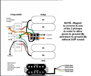
-The wiring that I explain uses the green wire as a ground for the bridge pickup BUT as the HOT wire for the neck one. It will only work if one of the magnets of the set has been reversed, or the sound will be OOP. This mod should also buck the hum when both North coils are in series…

I've added a mini ON/ON switch to the schematic and will try to explain what is going on. grey color on the schematic = white wires of pickups. I've renamed the two sides of the switch "X" and "Y" to make things clearer. Not sure it worked. :-P

IF I've done another error somewhere, THX by advance to correct it. My head is spinning too, more than ever... ;-)

Inner coils in series HH switchDCC.jpg

Mini switch on the LEFT : original diagram with the positions explained above as in the original pic… I've patiently checked the idea, it seems to work.

Mini switch on the RIGHT (new options):

Black of the bridge PU is now permanently connected to volume. Its Green wire is permanently connected to ground.

Position 5: nothing changes. B pickup enabled, coils in series.

Position 4: red and white wires of the bridge PU go altogether to the neck pickup, whose all wires are themselves going to ground and therefore, shorted . Black of the B pickup still goes to the volume so only its North coil is enabled. Nothing new, IOW. :-)

Position 3: black of the N to ground. Its green, white and red wires are altogether connected to the common side of Y, closing the South coil of N on itself. This common goes to the red and white wires of the B pickup. It opens to a new configuration: North coil of the neck PU is in parallel with South coil of bridge PU, from the ground. They join to be in series with the North coil of the bridge pickup, itself connected to the volume. It’s a 3 coils configuration, half parallel, half series.

Position 2: North coil of the N pickup enabled... its black goes to ground, its W/G/R go altogether to common lug of side Y, going itself to common of side X, going itself to R and W of the bridge pickup, going themselves to the volume with the black of the B pickup. North coil of B pickup shorted, consequently. But the green wire of the bridge still goes to ground and its red to volume. Result: North coil of N and South coil of B in PARALLEL.

Position 1: neck pickup enabled, both coils in series. Same thing for the bridge pickup. IOW: both HUMBUCKERS should be now in PARALLEL.

Where have I done a (new) mistake? LOL...

FWIW. It was a mind boggling but funny intellectual challenge. Maybe it will be useful too, unless I've lost my mind in the process. Time will tell... ;-)
 
You should be able to get what you want with a 5-way super switch. (I'd refer to your diagram, but it's mislabeled.)

What do you want each switch position to be?
1. Bridge (full humbucker)
2. ?
3. Bridge (full) + neck (full),
4. ?
5. Neck (full)

???
 
FOREWORD – I had posted this morning the message below and have redone it for two reasons:
-The color code was NOT suited to Duncan pickups. Corrected.
-The wiring that I explain uses the green wire as a ground for the bridge pickup BUT as the HOT wire for the neck one. It will only work if one of the magnets of the set has been reversed, or the sound will be OOP. This mod should also buck the hum when both North coils are in series…

I've added a mini ON/ON switch to the schematic and will try to explain what is going on. grey color on the schematic = white wires of pickups. I've renamed the two sides of the switch "X" and "Y" to make things clearer. Not sure it worked. :-P

IF I've done another error somewhere, THX by advance to correct it. My head is spinning too, more than ever... ;-)


Mini switch on the LEFT : original diagram with the positions explained above as in the original pic… I've patiently checked the idea, it seems to work.

Mini switch on the RIGHT (new options):

Black of the bridge PU is now permanently connected to volume. Its Green wire is permanently connected to ground.

Position 5: nothing changes. B pickup enabled, coils in series.

Position 4: red and white wires of the bridge PU go altogether to the neck pickup, whose all wires are themselves going to ground and therefore, shorted . Black of the B pickup still goes to the volume so only its North coil is enabled. Nothing new, IOW. :-)

Position 3: black of the N to ground. Its green, white and red wires are altogether connected to the common side of Y, closing the South coil of N on itself. This common goes to the red and white wires of the B pickup. It opens to a new configuration: North coil of the neck PU is in parallel with South coil of bridge PU, from the ground. They join to be in series with the North coil of the bridge pickup, itself connected to the volume. It’s a 3 coils configuration, half parallel, half series.

Position 2: North coil of the N pickup enabled... its black goes to ground, its W/G/R go altogether to common lug of side Y, going itself to common of side X, going itself to R and W of the bridge pickup, going themselves to the volume with the black of the B pickup. North coil of B pickup shorted, consequently. But the green wire of the bridge still goes to ground and its red to volume. Result: North coil of N and South coil of B in PARALLEL.

Position 1: neck pickup enabled, both coils in series. Same thing for the bridge pickup. IOW: both HUMBUCKERS should be now in PARALLEL.

Where have I done a (new) mistake? LOL...

FWIW. It was a mind boggling but funny intellectual challenge. Maybe it will be useful too, unless I've lost my mind in the process. Time will tell... ;-)

I'm confused that the switch position #1 is neck and #5 is bridge. Convention suggests position #1 is bridge pup.
Also, the OP's diagram shows/labels N2 + B1 (which are the outer coils) as the inner coils.
 
Yeah, I also prefer to label bridge position as position 1 but we all know that reversing the switch would solve this issue. :-D

Regarding the original schematic: it's confusing for several reasons, anyway (strange color code, discussible labelling, absence of precisions about magnetic polarities while it seems to require OOP pickups). Reason why I've partly corrected it. Now, the goal was to share a functional idea and not necessarily a perfect diagram: I've checked the signal path several times and still believe that it would work as I've pictured it above. But if I've left some bug in it, thx for helping to correct my attempt. And if it's a total fail, I'll simply cancel it. :-)

Thanks so, much- this is fantastic!

One quick question: would it be easy to slightly alter the configuration so that it uses the outer coil of the neck, instead of the inner? Would that still require the magnet to be reversed?
 
You should be able to get what you want with a 5-way super switch. (I'd refer to your diagram, but it's mislabeled.)

What do you want each switch position to be?
1. Bridge (full humbucker)
2. ?
3. Bridge (full) + neck (full),
4. ?
5. Neck (full)

???

Would it be possible for position 2. to be "inner coils in series" and position 4. to be "inner bridge coil and outer neck coil in parallel" ?

Something like:

1. Bridge (full humbucker)
2. Inner coils in series
3. Bridge (full) + neck (full),
4. Inner bridge coil and outer neck coil in parallel
5. Neck (full)
 
Thanks so, much- this is fantastic!

One quick question: would it be easy to slightly alter the configuration so that it uses the outer coil of the neck, instead of the inner? Would that still require the magnet to be reversed?

You're welcome...

Swapping the green and black wires of the neck PU should effectively give you the same thing than above but with the South / screw poles coil instead of the North/slugs one and without the necessity to reverse one of the mags. :-)
 
FOREWORD – I had posted this morning the message below and have redone it for two reasons:
-The color code was NOT suited to Duncan pickups. Corrected.
-The wiring that I explain uses the green wire as a ground for the bridge pickup BUT as the HOT wire for the neck one. It will only work if one of the magnets of the set has been reversed, or the sound will be OOP. This mod should also buck the hum when both North coils are in series…

I've added a mini ON/ON switch to the schematic and will try to explain what is going on. grey color on the schematic = white wires of pickups. I've renamed the two sides of the switch "X" and "Y" to make things clearer. Not sure it worked. :-P

IF I've done another error somewhere, THX by advance to correct it. My head is spinning too, more than ever... ;-)


Mini switch on the LEFT : original diagram with the positions explained above as in the original pic… I've patiently checked the idea, it seems to work.

Mini switch on the RIGHT (new options):

Black of the bridge PU is now permanently connected to volume. Its Green wire is permanently connected to ground.

Position 5: nothing changes. B pickup enabled, coils in series.

Position 4: red and white wires of the bridge PU go altogether to the neck pickup, whose all wires are themselves going to ground and therefore, shorted . Black of the B pickup still goes to the volume so only its North coil is enabled. Nothing new, IOW. :-)

Position 3: black of the N to ground. Its green, white and red wires are altogether connected to the common side of Y, closing the South coil of N on itself. This common goes to the red and white wires of the B pickup. It opens to a new configuration: North coil of the neck PU is in parallel with South coil of bridge PU, from the ground. They join to be in series with the North coil of the bridge pickup, itself connected to the volume. It’s a 3 coils configuration, half parallel, half series.

Position 2: North coil of the N pickup enabled... its black goes to ground, its W/G/R go altogether to common lug of side Y, going itself to common of side X, going itself to R and W of the bridge pickup, going themselves to the volume with the black of the B pickup. North coil of B pickup shorted, consequently. But the green wire of the bridge still goes to ground and its red to volume. Result: North coil of N and South coil of B in PARALLEL.

Position 1: neck pickup enabled, both coils in series. Same thing for the bridge pickup. IOW: both HUMBUCKERS should be now in PARALLEL.

Where have I done a (new) mistake? LOL...

FWIW. It was a mind boggling but funny intellectual challenge. Maybe it will be useful too, unless I've lost my mind in the process. Time will tell... ;-)

Maybe I'm wrong, but I'm not confident this does exactly what is proposed or what the OP was trying to do. For example, in position 5, without the toggle thrown to vol/gnd, it looks like the bridge pickup is running through the neck in series and in reverse phase to ground. Position 5 should have been the bridge humbucker by itself. The intent of the toggle was throwing the toggle would simply add the bridge humbucker (or neck, depending on how you do the toggle) to the other positions, but not change the 5-way he had.

With the original wiring, it might have been easier to add the neck to the other positions because the neck was already wired with hot to hot and ground to ground. It just needed a kind of 'blower' switch. But the problem I saw was having the pickups linked in series on the 5-way on the common lug - it makes it so you can't isolate the pickups anymore and control them differently, like with a blower. Now, it appears the only way to get the bridge humbucker is with the toggle switched, which also overrides the 5-way. It looks like you have to do 2 switch moves (toggle and 5-way) to go from position 5 to position 4, as described. Unless someone can point out how I'm reading this wrong? (Totally possible - that's a difficult drawing to start with)
 
Beaubrummels: thx for your feedback!

In position 5, with the switch on the left, here is what is going on as I understand it:
-Black wire of neck pickup connected to ground.
-Black wire of neck PU also connected to its green wire through the common lug of side Y. So the neck pickup is finally connected (closed, looped) on itself as a single path to ground.
Common lug of side Y is connected to common lug of side X, itself connected to green wire of Bridge PU. But position 5 on side X is connected to nothing. Black wire of bridge pickup goes to volume through the lug 1 of side X.
Total: Neck pickup shorted on itself and therefore changed in a simple path to ground. Bridge pickup enabled in full HB mode.

This doesn't change in my understanding if the switch is enabled: the green wire of the bridge pickup simply has a direct connection to ground instead of passing through the neck pickup closed on itself as a path to ground. the black wire still goes to the volume control through another wire. That's why I've used the same color.

IOW, in position 5 as I grasp it, the mini switch doesn't change anything compared to the original wiring.


I don't know either to which extent it's helpful. I was just trying to develop the idea of using a mini-switch to expand the original schematic. :-)
 
Back
Top