Wiring question 3 single coils

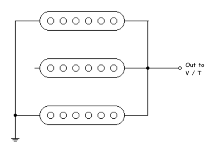
That diagram is a little hard to follow. But I see two problems right off. The middle pup is on the hot side of the circuit all the time. You're switching it off by lifting it's ground. That's not a good thing to do, and it's unnecessary.

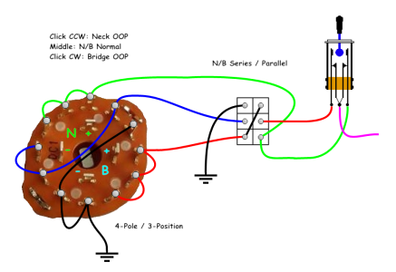
Your "top" DPDT, ( the one that isn't A or B, appears to put N/B on at the same time, but does it in a weird way, and causes a "dead" position on the Gibson toggle. That can also cause noise and hum if you accidently hit that position.

Let me look it over some more. I'll see if I can redraw it to resolve those issues. Are "A" and "B" supposed to be the 4PDT switch?
 
Thanks for checking.

"A" and "B" are supposed to be the 4 pole 3 way rotary indeed.

I have no idea why what you say is a bad thing, but I'll take your word for it!

The 'top' DPDT is to put neck and middle in series or parallel in the middle position of the 'gibson' toggle.
 
I'm not sure if the new forum software will let me post a pic, so I'll add a link to my public OneDrive. But it isn't complaex. It will just show three singles all connected at the same time, with the middle pickup ground disconnected.

In the back of old AM radio's, there was a big coil, for the antenna. Similar to a guitar pickup. If you "float" a guitar pickup, on the 'hot" side of the circuit, you have that antenna. It's just not a good thing to do, and unnecessary with the switches you have.

 
No, no. It was a simple drawing of 3 single coils wired in parallel, with the ground connection of the middle pup lifted. It just made it easy to visualize the "problem", so to speak.

We may have to wait for the new forum software to get the growing pains worked out before I can post the revised diagram.
 
I think we can post images already. As long as they're under 2mb. I'm hoping to finish this project this weekend. I'm so, so done with this haha. Been working 80 to 100 hours a week for 2 months. I'm looking forward to a break.
 
I'll try again. The file is only 9kb. This isn't the final diagram. It's only to visualize the "problem", so to speak, of floating a pickup ground.
 

Attachments

  • Temp.png
    Temp.png
    8.9 KB · Views: 6
I'm not going to make a strat with the 3 singles but a les paul. The schematic I posted earlier is to go in a lp and the out of phase options are some of my all time favorites.
 
Hey orpheo. I'm at my "drawing board" now. Pretty sure I understand what you want. But I need you to confirm one little thing. I don't want you to get this all wired up, then not have it work as expected, or at all.

I'm sure you have a meter. With the 3-way and 4-way facing you, (knob side towards you), put the 3-way into it's middle position. Then click the 4-way into it's most clockwise position. Verify the contacts are as the attached diagram show. I'll email you the diagram if the new software doesn't accept it.
 

Attachments

  • 3-way_4-way_temp.jpg
    3-way_4-way_temp.jpg
    80.5 KB · Views: 3
You analysed the 3 way correct but the 4 way not. I took a photo.
 

Attachments

  • 20251027_230801.jpg
    20251027_230801.jpg
    218.2 KB · Views: 4
Cool. So the common is adjacent to pole #4? I've got the rest of the diagram done up to this point.
 
One more thing that would help me . . . I know you're doing this into an LP. Are you doing master volume/master tone up top? Then the two rotary's, at the bottom, with the mini-toggle in-between the two rotary's? (Ignore the HB'ers. Stock photo.)

Kinda like this:
 

Attachments

  • Layout-01.png
    Layout-01.png
    87.1 KB · Views: 5
Yes, that is the idea. I thought of doing the series parallel switch with a push pull pot but I dislike those quite a bit. So just a toggle indeed
 
Thought I'd bump this thread with a photo of the guitar & pickups in question. The guitar behind her has a Concept set, but is otherwise identical. Needs new pickup rings though.
 

Attachments

  • 20251029_224538.webp
    20251029_224538.webp
    327.8 KB · Views: 1
Back
Top