Gaps in the Wiring Diagrams?

Re: Gaps in the Wiring Diagrams?

I thought of a ridiculous HH wiring that allows all settings I can theoretically think of, to a total of (edit) 156. Haven't yet made a diagram, maybe I'll do one soon.

Why? I think I might turn my Epiphone into a test guitar to find out my favourite settings for possible future wirings.

Here it is:

HH156.jpg

The beauty in it is that you get 156 settings without drilling any holes into your Gibson, hence I call it the "Gibsanity". You need two 4P6T rotary switches, two P/P pots, and keep the 3-way toggle switch. The OOP P/P puts the neck pup out of phase with the bridge, the serial P/P puts bridge and neck in series and overrides the 3-way toggle.

Each HB gets its own rotary switch:

1. standard HB (series, in phase)
2. Coil split north (inside coil)
3. Coil split south (outside coil)
4. Both coils parallel
5. Both coils in series, out of phase with itself
6. Both coils in parallel, out of phase with itself

With two pups, you get 6X6=36 settings. Neck out of phase switch doubles that to 72, series switch doubles that again to 144. Add to that 6 settings for each single pup to a total of 156.

If you spot a mistake in my wiring, please tell me.

edit: no idea why that isn't in SD's official wiring diagrams...
 
Last edited:
Re: Gaps in the Wiring Diagrams?

Here it is:
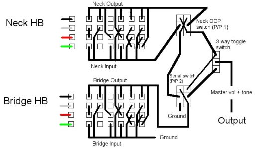
View attachment 63119

The beauty in it is that you get 156 settings without drilling any holes into your Gibson, hence I call it the "Gibsanity". You need two 4P6T rotary switches, two P/P pots, and keep the 3-way toggle switch. The OOP P/P puts the neck pup out of phase with the bridge, the serial P/P puts bridge and neck in series and overrides the 3-way toggle.

Each HB gets its own rotary switch:

1. standard HB (series, in phase)
2. Coil split north (inside coil)
3. Coil split south (outside coil)
4. Both coils parallel
5. Both coils in series, out of phase with itself
6. Both coils in parallel, out of phase with itself

With two pups, you get 6X6=36 settings. Neck out of phase switch doubles that to 72, series switch doubles that again to 144. Add to that 6 settings for each single pup to a total of 156.

If you spot a mistake in my wiring, please tell me.

What if you used a 5 way switch?
 
Re: Gaps in the Wiring Diagrams?

That would need additional drilling in a Gibson/Epiphone, wouldn't it? I'll be thinking about a 5-way+vol+tone Jackson for example though.

Can't wait to get my hands on a three-HB Gibson though to create a spacetime-bending bazillion setting guitar.
 
Re: Gaps in the Wiring Diagrams?

I thought of a ridiculous HH wiring that allows all settings I can theoretically think of, to a total of (edit) 156. Haven't yet made a diagram, maybe I'll do one soon.

Why? I think I might turn my Epiphone into a test guitar to find out my favourite settings for possible future wirings.


OMG, omg81! (Sorry, couldn't resist!) Pretty extensive... and I can't think of any other combos to add either. The one I did for my H-H-H hits a lot of these, but not all. I think you already know what you're going to discover if/when you do it... you mentioned it in your first post about your possible test Epiphone. Lots of the sounds you'll find will be very close to one another, and you'll end up gravitating to just a few... but you will have found it out for yourself! I know that I will probably never make another guitar with as many options as I did with my Westone, but I enjoyed making it and have learned the sounds I like. If you go into it knowing that... then GO FOR IT!
 
Re: Gaps in the Wiring Diagrams?

That would need additional drilling in a Gibson/Epiphone, wouldn't it? I'll be thinking about a 5-way+vol+tone Jackson for example though.

Can't wait to get my hands on a three-HB Gibson though to create a spacetime-bending bazillion setting guitar.

Oh you're talking about a toggle switch. I thought you meant a 3 way like on a Fender Strat.

Although you could go to a rotary switch in that position.
 
Re: Gaps in the Wiring Diagrams?

What about a three full size Humbucker setup on a Strat without adding any other controls... except... for three Triple Shot Mounting Rings around each Humbucker ?

I say full size because they have a three mini humbucker diagram in there...

Not bad, but then if they already have a diagram for 3 4-conductor 2-coil pickups (i.e. mini hums or Lil/Jrs), then the only difference here would be the TripleShots. Diagrams for those are plentiful (and in fact are designed to only work a specific way), and in the end they terminate into a 2-conductor wiring scheme of hot/ground, with the only known option there of phase reversal via DPDT, for which there is a universal diagram.

Wiring this up would just require using two existing diagrams; the standard TS wiring and the standard 2-conductor 3-pickup Strat diagram, plus the universal phase diagram.

I'm certainly not opposed to the idea, but from a visual document perspective, this wiring scheme isn't missing from the list, there's just no imagery of 3 full-sized HBs on TSs on a Strat layout.
 
Re: Gaps in the Wiring Diagrams?

From what I've seen, for the most part, most of the diagrams here are for traditional setups and traditional control layouts - LP-style 2H + 4 pots + 3-way; S-S-S + 5-way blade + V-T-T, etc. There's quite a few variants, of course, what with the push-pulls and this and that, but what diagrams do you not see here? I know I've seen quite a few requests over time that there's not a diagram for, though I can never recall them when I actually have time to sit down and try to catalog them.

So post those wiring schemes here, if you remember one that you got help for that wasn't covered (i.e. P-Rails with a 6-way rotary and 3-way Gibson toggle, H-S-S with master this or that), and I'll see if I can put them together in somewhat of a standardized drawing format. Can't promise they'll look as good as SD diagrams, but they should come out better than Paint.

Maybe together we can build a library of every possible (feasible) pickup and control combo.

Cool idea! Let me know if I can be of any help - maybe we can put together a public library of sorts or if you want I can request we build them out in the near future for you all.
 
Re: Gaps in the Wiring Diagrams?

Here it is:

View attachment 63119

The beauty in it is that you get 156 settings without drilling any holes into your Gibson, hence I call it the "Gibsanity". You need two 4P6T rotary switches, two P/P pots, and keep the 3-way toggle switch. The OOP P/P puts the neck pup out of phase with the bridge, the serial P/P puts bridge and neck in series and overrides the 3-way toggle.

Each HB gets its own rotary switch:

1. standard HB (series, in phase)
2. Coil split north (inside coil)
3. Coil split south (outside coil)
4. Both coils parallel
5. Both coils in series, out of phase with itself
6. Both coils in parallel, out of phase with itself

With two pups, you get 6X6=36 settings. Neck out of phase switch doubles that to 72, series switch doubles that again to 144. Add to that 6 settings for each single pup to a total of 156.

If you spot a mistake in my wiring, please tell me.

edit: no idea why that isn't in SD's official wiring diagrams...

Probably because most of SD's diagrams focus on functions that are easy to achieve in a live performance, where it's easier to grab a different guitar that's pre-wired for a given set of wiring options than scanning a chart and setting R1 to 3 and R2 to 4 and pulling SW1 up while pushing SW2 down. I suppose if you had absolutely nothing else in life to memorize, and did that 5 days a week several hours a day, it'd be no trouble, but I'm sure SD has this vision of their products being used by working professionals just as much as basement tone freaks.

I'm certainly not bashing the concept at all - it's genius, if it works. But that doesn't mean Slash (as an example) cares whether nor not he can get 156 tonal options out of one guitar. I'm not sure if SD's techs who draw up diagrams care about that, either.

For this diagram, you're using 2 6-way double-wafer rotary switches (which I think will fit in an SG, though you may want to bend the tabs of the bottom wafer flat or shave a bit of wood out of the cavity), but there's no point of reference for the tabs of the rotary. What's the Common for each Pole?
 
Re: Gaps in the Wiring Diagrams?

FWIW - A common one that is missing is HSS with 500K vol for the hum and 250k vol for the middle/neck.

Ok, I don't have any HSS 3-knob guitars, so this may not be correct. It looks feasible to me, based on what I've gleaned from looking at a few different standard diagrams and the connection grouping for this type of switch. The main point I'm concerned about here is if this is the correct way to share the Tone control.

HSS_500KV_250KV_1T_5way.jpg


With a standard VTT diagram, all the pickups go to the switch first. Here, the bridge pickup goes to the 500K Volume first, and then that goes to the switch.

From the look of things, the two halves of the switch are not internally connected (diagrams always show a jumper joining both Commons then out to the master Vol), so I'm assuming that you'd run the bridge hum's 500K volume pot to one side of the switch by itself (position 1) and then the Common out to the Tone. Then run the singles to the switch as you normally would on the other side, then that Common out to the 250K Volume, leaving out the jumper that connects the two Commons.

The part I'm not sure about is where the Tone connects to the 250K pot. It looks to me like there'd be a conflict here, in that the bridge pickup would connect to the 250K pot through the Tone, which is of course not what I'm going for.
 
Re: Gaps in the Wiring Diagrams?

The liberator is meant to be used as a volume control. But the key is how to wire for other configurations other that the default HH. I know color codes would not match but hey, SD already offered pre wired pickguards like the BYOP (Bring your own pickups) so it is doable, it is just a matter to kno how do they recommend wiring for HSS, HSH or SSS (true or stacked)


Edit: Currently I am using the liberator to wire neck and bridge only of HSS or HSH, I do permanently wire a SSL-1 in the middle. I would like to see what SD suggest so all 3 pickps can be used solderless thru the liberator.

Well, I don't work for SD, so I can't say what they recommend for any setup. For a 3-pickup 5-way switch configuration, you might consider running from the pickup switch into the Liberator's pot terminal block, then back to the Tone controls from there. That would work for a Strat-style 1V2T or Jackson-style 1V1T setup. However, that's just a basic setup without coil-splitting the pickups, so you won't need to run into the big terminal block. If you wanted coil-splitting with push/pull Tones, then you'd run those switching options first, then the switches go out to the pickup selector, and then the pickup selector to the Liberator.

However, the only thing you're gaining there is not having to solder to the Liberator. If you're soldering push/pulls, the pickup switch, as well as all new pots, one more wire won't matter.
 
Re: Gaps in the Wiring Diagrams?

Probably because most of SD's diagrams focus on functions that are easy to achieve in a live performance, where it's easier to grab a different guitar that's pre-wired for a given set of wiring options than scanning a chart and setting R1 to 3 and R2 to 4 and pulling SW1 up while pushing SW2 down. I suppose if you had absolutely nothing else in life to memorize, and did that 5 days a week several hours a day, it'd be no trouble, but I'm sure SD has this vision of their products being used by working professionals just as much as basement tone freaks.

I'm certainly not bashing the concept at all - it's genius, if it works. But that doesn't mean Slash (as an example) cares whether nor not he can get 156 tonal options out of one guitar. I'm not sure if SD's techs who draw up diagrams care about that, either.

lol sorry, I was joking there, maybe I should've been more obvious about that. I wouldn't want to use that guitar much either, I like to just have one switch and done. But a test guitar like this would certainly help me find the right settings for my future wirings. As in, are both neck-side or both bridge-side coils better? What if you wire two HBs in series and out of phase (seen a video of that and it sounded pretty cool)? How will three coils in series sound like? Or how about neck HB + out of phase with itself bridge HB in series, to have a neck with a little bit more treble crisp? It doesn't make too much sense, I guess it's more the fiddler than the guitar player in me that's excited about it.

I'm going to buy a Jackson DK2M at some point which has a JB/59 set, replace those with Black Winters, and the JB and 59 will then go into the SG, which will then get this wiring.

For this diagram, you're using 2 6-way double-wafer rotary switches (which I think will fit in an SG, though you may want to bend the tabs of the bottom wafer flat or shave a bit of wood out of the cavity), but there's no point of reference for the tabs of the rotary. What's the Common for each Pole?

Left to the wiring? (SD colours) The four pickup wires are the commons. Leftmost column is common, then to the right it's position 1-6.
 
Last edited:
Re: Gaps in the Wiring Diagrams?

Well, I don't work for SD, so I can't say what they recommend for any setup. For a 3-pickup 5-way switch configuration, you might consider running from the pickup switch into the Liberator's pot terminal block, then back to the Tone controls from there. That would work for a Strat-style 1V2T or Jackson-style 1V1T setup. However, that's just a basic setup without coil-splitting the pickups, so you won't need to run into the big terminal block. If you wanted coil-splitting with push/pull Tones, then you'd run those switching options first, then the switches go out to the pickup selector, and then the pickup selector to the Liberator.

However, the only thing you're gaining there is not having to solder to the Liberator. If you're soldering push/pulls, the pickup switch, as well as all new pots, one more wire won't matter.

Here's one:

Liberator-HSS01.jpg


Standard H-S-S wiring with 1V (Liberator) and 2 Tones and a 5-way.

Pickups to selector, selector to Liberator as main volume, Liberator to output.

No higher-functions are illustrated (splitting, etc) as the focus was merely to show the Liberator in this layout.
 
Re: Gaps in the Wiring Diagrams?

The part I'm not sure about is where the Tone connects to the 250K pot. It looks to me like there'd be a conflict here, in that the bridge pickup would connect to the 250K pot through the Tone, which is of course not what I'm going for.

It looks to me like that's a possibility also. It would certainly be fine when running just the HB or just single coil(s), but the question is does something funky happen when both are one at once? How about a 500k dual concentric pot on the HB, inner volume and outer tone? It would make the question moot and give better tonal variety to the guitar.

Just a thought... :D
 
Re: Gaps in the Wiring Diagrams?

Left to the wiring? (SD colours) The four pickup wires are the commons. Leftmost column is common, then to the right it's position 1-6.

Ok. I thought the colored wires were merely to show pickup starts from the pickups, not Commons for the switch.

So the next question is, which row of blocks represent which set of contacts for the Rotary wafers? Top 2 rows are outer wafer and bottom 2 rows are inner (closer to knob)? Outer rows are outer wafer and inner rows are inner wafer? Also, what are the "Input" and "Output" for each pickup supposed to mean? Pickups only have Output.

I'd like to make these diagrams so they can be understood strictly by sight without the need for foreign-language translations or explanations, and in such a manner that the component you see in the diagram looks like the one you're holding in your hand, at least in general shape (i.e. pins arranged in an oval fashion for the rotary switch), and color-coding of all connections. I find it's easier to follow along that way.
 
Re: Gaps in the Wiring Diagrams?

It looks to me like that's a possibility also. It would certainly be fine when running just the HB or just single coil(s), but the question is does something funky happen when both are one at once? How about a 500k dual concentric pot on the HB, inner volume and outer tone? It would make the question moot and give better tonal variety to the guitar.

Just a thought... :D

There are also 250+500K concentric pots, but not everyone wants the extra girth and height those add, or want to keep their vintage-style names and numbers knobs, and concentrics that will fit through a wood top are harder to find.
 
Re: Gaps in the Wiring Diagrams?

Sorry, I didn't mean it to be a "real" wiring diagram, it was just a sketch. Wasn't meant as installation instructions. I'd try to make a full diagram if someone wanted one, but I don't think anyone's going to do that anyway.
 
Re: Gaps in the Wiring Diagrams?

You never know. If it's in a "paint-by-numbers" format, more people would be apt to try it out. Just because Dave Mustaine wouldn't use it doesn't mean I wouldn't :lol:

I can make the diagram, I just gotta know what physical section of the real thing each row relates to. I got started on it already but hit the one snag. I've got it laid out so that black and white are on one wafer, and red and green on the other. I just need to know how each one translates to the 6-way rotator to make sure I should be jumping across wafers, and in the right patterns.

Looking closely at the 6-way rotary I have, and comparing it to the rows you've drawn, the contacts are laid out like this:
Outer wafer
123456
654321

Inner wafer
123456
654321

at least according to how the wiper touches them.

If the top 2 rows of your layout are
123456
123456

I just need to reverse it for the diagram.
 
Re: Gaps in the Wiring Diagrams?

I haven't even had a rotary switch yet, that was entirely theoretical. I only have a faint idea where the connectors are on that thing. You really don't have to do that, if you think there might be sense in it, I can happily (try to) create a full diagram.

But if you want to know, in my sketch it's:

C1 Blk 1 2 3 4 5 6
C2 Wht 1 2 3 4 5 6
C3 Red 1 2 3 4 5 6
C4 Grn 1 2 3 4 5 6


So, position 1 means that column 1 is connected to common, regardless of actual position on the switch. Just to visualise the idea. So for example, position/column 2 for the bridge pickup means that white is connected to ground and black to output.

I think you also asked where the "neck input" and "neck output" comes from, that was just an auxiliary for me to keep track on what needs to go where. The idea is that each pickup always has one "out" (hot) and one "in" (cold?) regardless of which coils are used in which order. I needed that for wiring series and OOP switch, which have "in" and "out" connectors. "Neck input" is connected either to ground (series switch off) or to bridge output (series switch on), and OOP switch simply reverses neck in and out.

Standard (parallel) wiring:

Bridge "input" = ground
Bridge output -> toggle switch
Neck "input" = ground
Neck output -> toggle switch

Series switch on:

Bridge input = ground
Bridge output = neck input
Neck output -> toggle switch (to both neck and bridge poles, to prevent the bridge position acting as a kill switch--that's where the additional wire from toggle switch to series switch comes from. That's how I wired the series switch in my Phat Cat-equipped SG, so at least I know the series switch works. If you like the idea of having a kill switch there, you can just leave that wire out, but I prefer the series switch to override the toggle completely)

So, the rotary switch positions for each pickup are:

1 - standard humbucker: input (usually ground) -> green, red -> white, black -> output
2 - coil split North: input -> white, black -> output
3 - coil split South: input -> green, red -> output
4 - both coils parallel: input to green and white, red and black to output
5 - out of phase series: input to red, green to white, black to output
6 - out of phase parallel: input to red and white, green and black to output
 
Last edited:
Re: Gaps in the Wiring Diagrams?

How about one for a two humbucker, 1volume, 1 tone with a five way blade switch that would get the PRS rotary switch settings of
1.) full bridge
2.) both outside coils in parallel
3.) full bridge and full neck
4.) inside coils in series
5.) full neck
I would like to try this instead of the one that splits the bridge or neck in positions 2&4, which is how my Schecter is currently wired.
 
Back
Top