Gaps in the Wiring Diagrams?

Re: Gaps in the Wiring Diagrams?

Haven't had a chance to work on the HSS 500k/250k one. But in the meantime I'll contribute this. This is the Jimmy Page wiring that follows the behavior described for Gibson's Jimmy Page #2 Les Paul. (The Duncan diagram doesn't have all the options possible, and I believe there is an omission/error in the Duncan one.)

Y2BsOb6.png


Note: this wiring scheme has an artifact that for series, the pickup selector switch needs to be in the middle position. In the neck position, you'll get nothing, in the middle or bridge position it will work as expected. There are versions of this wiring that avoid that problem, but my understanding is the Gibson guitar has this same issue. (Though one could argue it's user error to expect two pickups in series when only one is selected on the switch.)


This is an alternative version I have in my SG right now. I moved the split coil to the two pickguard switches because it's less wires through the channel.

tqP5e3w.png


There are number of different ways to get these options. There's a guy named Hermetico on here that has a good one that utilizes the PRail scheme where the Vol/Tone switches are wired to allow controlling which coil is used for single. Myself I've done about 15 different Page diagrams trying to work out the easiest to wire / easiest to use versions. These two may not be the best for you. Feel free to suggest improvements.
 
Re: Gaps in the Wiring Diagrams?

How about one for a two humbucker, 1volume, 1 tone with a five way blade switch that would get the PRS rotary switch settings of
1.) full bridge
2.) both outside coils in parallel
3.) full bridge and full neck
4.) inside coils in series
5.) full neck
I would like to try this instead of the one that splits the bridge or neck in positions 2&4, which is how my Schecter is currently wired.

Of the standard 5-way blades I've seen in person, positions 2 and 4 are automatic bridges between 1 and 3 and 3 and 5, which is why the SD diagrams typically show these giving an auto-split function. This might require a Superswitch to pull off. I think StewMac has a 5-way Megaswitch that's prewired for this, as well.

Alternatively, it could probably be done with a standard 5-way and a pair of push/pulls that were wired to the specific functions in the Down position, so you'd never have to pull them Up to get the effect. They could also be wired so that pulling them Up reverts to the auto-split function. I'll poke through the existing diagrams and see what I can cook up.
 
Re: Gaps in the Wiring Diagrams?

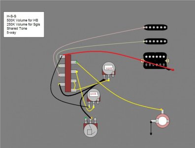
Ok, I don't have any HSS 3-knob guitars, so this may not be correct. It looks feasible to me, based on what I've gleaned from looking at a few different standard diagrams and the connection grouping for this type of switch. The main point I'm concerned about here is if this is the correct way to share the Tone control.

HSS_500KV_250KV_1T_5way.jpg


With a standard VTT diagram, all the pickups go to the switch first. Here, the bridge pickup goes to the 500K Volume first, and then that goes to the switch.

From the look of things, the two halves of the switch are not internally connected (diagrams always show a jumper joining both Commons then out to the master Vol), so I'm assuming that you'd run the bridge hum's 500K volume pot to one side of the switch by itself (position 1) and then the Common out to the Tone. Then run the singles to the switch as you normally would on the other side, then that Common out to the 250K Volume, leaving out the jumper that connects the two Commons.

The part I'm not sure about is where the Tone connects to the 250K pot. It looks to me like there'd be a conflict here, in that the bridge pickup would connect to the 250K pot through the Tone, which is of course not what I'm going for.

I apologize for stealing and horribly editing your diagram but here's how I just did a pickguard for a 2 Volume, one tone HSS
HSS_500KV_250KV_1T_5waykl.jpg

It basically somewhat isolates the two halves of the switch. The right side essentially chooses which pot to use by utilizing the common lug for the hot output. Then the two volume pots are connected to their respective places on the right side so only the correct volume pot is being used in a given switch position. So in the bridge position only the 500k volume is being utilized... and so on... However in the bridge, middle position one volume does affect the other. If one is turned down low enough the other goes down with it.
The left side is pretty much wired like a standard strat switch except for basically a jumper that connects the left side of the switch and the right side of the switch by going to the lug on the 250 volume pot and another jumper that connects the bridge pickup to the left lug on the 500k volume pot. It's also a master tone for all three pickups unfortunately... couldn't figure out how to make it only neck and middle...
 
Last edited:
Re: Gaps in the Wiring Diagrams?

Figured out how to get a tone for the neck and middle only. You have to do what you did with the 500k volume pot. Wire the bridge pickup directly to the volume pot instead of to the switch that way it does not see the tone pot because of the common lug on the switch.
 
Last edited:
Re: Gaps in the Wiring Diagrams?

Actually that diagram was intended to get separate volumes and a master tone.

Yeah I really just wanted to fix the diagram I used. the switch was backwards on the one I used and since your diagram already had everything needed in an easy to see format I figured plagiarism can't hurt right? ;).. and i thought I may as well throw my .02 into the bucket while I was at it. :)
 
Re: Gaps in the Wiring Diagrams?

Of the standard 5-way blades I've seen in person, positions 2 and 4 are automatic bridges between 1 and 3 and 3 and 5, which is why the SD diagrams typically show these giving an auto-split function. This might require a Superswitch to pull off. I think StewMac has a 5-way Megaswitch that's prewired for this, as well.

Alternatively, it could probably be done with a standard 5-way and a pair of push/pulls that were wired to the specific functions in the Down position, so you'd never have to pull them Up to get the effect. They could also be wired so that pulling them Up reverts to the auto-split function. I'll poke through the existing diagrams and see what I can cook up.

I'd be more than happy to get a super switch if the guitar doesn't already have one. While I think that the pickups sound ok split, I think I would like the other two options much more.
 
Re: Gaps in the Wiring Diagrams?

I've been working with some ideas (on paper, anyway) and I can't find a way to combine these two diagrams:

http://www.seymourduncan.com/support/wiring-diagrams/schematics.php?schematic=coil_splitting

using two push/pulls. I can get halfway there, but it doesn't end properly.

However, there's a Superswitch diagram at GuitarElectronics.com, presented here in my always-evolving non-standardized standard formatting :lol:
http://www.guitarelectronics.com/pr...ckers5-Way-Lever-Switch1-Volume1-Tone-06.html

PRS-Super5-1V1T.jpg
 
Re: Gaps in the Wiring Diagrams?

Yeah I really just wanted to fix the diagram I used. the switch was backwards on the one I used and since your diagram already had everything needed in an easy to see format I figured plagiarism can't hurt right? ;).. and i thought I may as well throw my .02 into the bucket while I was at it. :)

Ahh, I see I thought you were pointing out what my error was with sharing the Tone pot.
 
Re: Gaps in the Wiring Diagrams?

I apologize for stealing and horribly editing your diagram but here's how I just did a pickguard for a 2 Volume, one tone HSS
View attachment 63225

It basically somewhat isolates the two halves of the switch. The right side essentially chooses which pot to use by utilizing the common lug for the hot output. Then the two volume pots are connected to their respective places on the right side so only the correct volume pot is being used in a given switch position. So in the bridge position only the 500k volume is being utilized... and so on... However in the bridge, middle position one volume does affect the other. If one is turned down low enough the other goes down with it.
The left side is pretty much wired like a standard strat switch except for basically a jumper that connects the left side of the switch and the right side of the switch by going to the lug on the 250 volume pot and another jumper that connects the bridge pickup to the left lug on the 500k volume pot. It's also a master tone for all three pickups unfortunately... couldn't figure out how to make it only neck and middle...

This is where I landed so far. Mine only has the tone on the neck and middle, which is how strats normally are - no tone on the bridge (though I prefer a tone on a bridge humbucker myself). I do not know if this is correct, however. This has not been tested by me.

a4R7Vbj.png
 
Re: Gaps in the Wiring Diagrams?

Unfortunately the PRS-style diagram above doesn't get both hums full in #3. The Superswitch has been my nemesis for years :lol:

Though at one time I did have a diagram in the works where you could use all 4 poles as separate switches, selecting between them with push/pulls. It can only mount in an acoustic due to amount of wire required :lol:
 
Re: Gaps in the Wiring Diagrams?

This is where I landed so far. Mine only has the tone on the neck and middle, which is how strats normally are - no tone on the bridge (though I prefer a tone on a bridge humbucker myself). I do not know if this is correct, however. This has not been tested by me.

a4R7Vbj.png

I think my diagram may be correct, I just have no way to test it. It's like firebirdguy said - treat each half of the switch separately and don't jump them together like normal diagrams show. Only part I wasn't sure of was the way I have the Tone control shared. Electrons generally don't care if you want them to go in one direction - if there's a connection they can travel along, they're going there, so I don't know if by running the bridge-side of the switch to the Tone control it'll try to pass the signal back into the 250K pot, giving you a 750K pot total on the bridge. And if you've never tried doing that on purpose (like I did once), it's not good for tone, but very educational.

However, if it were for my own use, I'd consider a concentric 250K/250K Tone pot at the very end. It's out of the way, and each volume gets its own Tone, while still only taking up 3 holes instead of 4. But that's just me.
 
Re: Gaps in the Wiring Diagrams?

Another issue I've just noticed with the PRS-type diagram above - the R&W are always together, which I'm thinking would not allow certain switching functions. The SD diagrams for cutting specific coils indicates that Red is how for one with Green and Black together. Might be why the SD and GE diagrams state flipping the magnet or pickup to get parallel between opposing coils.

Hmmm. Gonna dig more into it.
 
Re: Gaps in the Wiring Diagrams?

Only part I wasn't sure of was the way I have the Tone control shared. Electrons generally don't care if you want them to go in one direction - if there's a connection they can travel along, they're going there, so I don't know if by running the bridge-side of the switch to the Tone control it'll try to pass the signal back into the 250K pot, giving you a 750K pot total on the bridge.

I was concerned about this to. And at least in my diagram i believe it would have been a total of 750k like you said. I think this because when I swapped the tone control to the neck/middle lug on the right side of the switch I still had tone control for the bridge. Which means it was back feeding all the way through the common, through the 250k pot then to the tone control. Not a good combo for good tone... thankfully I saw your diagram and used a part of it to isolate the humbucker from the switch almost entirely. So now the tone only works for the neck and middle. Thanks for the help! It saved my ass today!
 
Re: Gaps in the Wiring Diagrams?

This is where I landed so far. Mine only has the tone on the neck and middle, which is how strats normally are - no tone on the bridge (though I prefer a tone on a bridge humbucker myself). I do not know if this is correct, however. This has not been tested by me.

a4R7Vbj.png

So am I reading this right?

The left side of the switch is used exclusively for the humbucker and has a respective hot wire that goes from the left common lug to the output Jack. Meanwhile the right side is used for the neck and middle and has a traditional hot wire for the Jack that comes from the middle lug on the 250k volume. The tone pot is then connected to the 250k volume.
The only thing that would concern me would be that it has two hot wires to the Jack. It might back feed and do some funky stuff. Like have all the pickups on at the same time regardless of the switch position because it's connected both volume pots and both sides of the common lugs on the switch simultaneously. Maybe I'm wrong and missing something...I don't know... it's just my .02
 
Re: Gaps in the Wiring Diagrams?

So am I reading this right?

The left side of the switch is used exclusively for the humbucker and has a respective hot wire that goes from the left common lug to the output Jack. Meanwhile the right side is used for the neck and middle and has a traditional hot wire for the Jack that comes from the middle lug on the 250k volume. The tone pot is then connected to the 250k volume.
The only thing that would concern me would be that it has two hot wires to the Jack. It might back feed and do some funky stuff. Like have all the pickups on at the same time regardless of the switch position because it's connected both volume pots and both sides of the common lugs on the switch simultaneously. Maybe I'm wrong and missing something...I don't know... it's just my .02

Could be. I thought the switch breaks the connection back to the pickups. I believe whether the pickups are combined into one wire at the switch with a jumper, or combined at the jack without a jumper, as long as the switch lifts one or the other pickup out of the equation it should work. (As it happens, the tone stack on my 62RI Strat just went bad, so I may have a chance to test this in the near future. Will be a few weeks before I can get to it, unfortunately.)
 
Re: Gaps in the Wiring Diagrams?

My feeling on that is that when the switch lifts one, it will lift both simply because they terminate at the same point - the jack. However, that's simply based on my primitive understanding of electrical theory (and when I say primitive, I mean knuckledragging Cro-Magnon barely walking upright kinda primitive).

If only there was a way to auto-switch the Tone control from the 500K to the 250K when either option was selected. The only issue then would be deciding who gets the Tone when the bridge is combined with a single.

I would say run it like I had it - bridge to 500K, 500K to right of switch, but then run the right common to Pos1 on the left instead of the Tone, but we end up with the possibility of 750K again.

Ahh, another option (maybe) would be to put resistors in Pos2 right-side, cutting the 500K down to 250K, so that when the pots combined, you'd get ~500K total. Cut the left side in the same position with resistors down to ~100 and get a happy medium in the 300 range? Once you get into pure singles, you're not using the resistors so it goes back to 250K. Would that work?

Or if the bridge happens to be a JB, try a 250K pot like everyone and their mother says works best :lol:
 
Re: Gaps in the Wiring Diagrams?

I've decided to simplify things and go with Triple Shots and a three way switch. I won't get the exact PRS combinations, but I could with just one push/pull, if I decide to put one in.
 
Re: Gaps in the Wiring Diagrams?

@DrNewcenstein

I want to make a full wiring diagram for my idea, but there seem to be different types of rotary switches and wiring diagrams (e.g. two separate wafer diagrams) for them. Would a template like the one used for this diagram be correct?

attachment.php
 
Last edited:
Back
Top