Re: Help need on funky coil split wiring. Make push pull see 250K pots
Hey guys, I was hoping one of you most knowledgable people might be able to help me out. I can wield a soldering iron, but I’m useless at actually figuring out any kind of electronics!!
Here’s the thing...
My guitar has 2 Humbuckers, 1 vol(500k) 1 push/pull tone (500k) pull for coil split, 3 way toggle, 4 conductor wiring.
I would like to do 2 things if possible.
1. Remove the tone control from the circuit when on humbuckers
2. When coil split, make the pickups see 250K Vol & Tone values.
Does anyone know if both of these things are possible at the same time?
Would anyone be able to break down the wiring in super basic terms, or point me to a wiring diagram? I’ve had a look around, but can’t quite find what I’m looking for.
Thanks guys!
Dean
Yes, it can be done and below is my recommended way to do it.
You need a switch that has many poles to do multiple things at once. If you kept both pots as 500K value, you would need a 5 pole double throw (5PDT) switch, which i am not sure even exists. However, in the scenario you described, the Tone Pot has no need to remain as a 500K value at all since it only gets used during Split Coil mode and at a 250K value, so my recommendation changes the Tone Pot to a 250K value, and that means we only need a 4PDT switch, which. is commonly available.
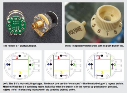
4PDT switches are available as traditional two-way toggle switches, or in the format of a push-push Fender S1 switch that has a pot for use as a volume or tone ctl. In my recommended scheme, you will no longer need your current push-pull for coil splits, and so i replace that push-pull with a Fender S1 push-push switch. Per a recent thread on this forum, mutliple forum members reported the S1 switch is very relaiable and durable, even through it does cost in the +$20 area.
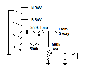
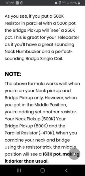
You can make a 500K pot see 250K by wiring a 470K resistor in between (in the case of a volume pot) the 1st and 3rd lugs. In the case of a Tone Pot, the resistor would be wired between the two active lugs (1 and 2), but we don't need to do that here per what i mentioned above.
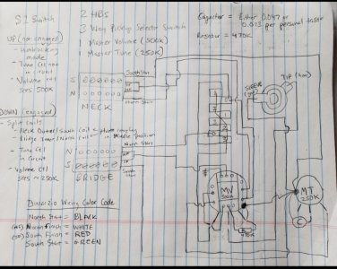
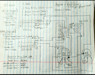
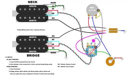
So in the diagram below, one pole of the 4 pole S1 switch brings the resistor into the circuit for the Volume ctl when the S1 switch is engaged.
Another pole of the S1 Switch brings the Tone Control into circuit when the S1 switch is engaged.
And finally the last two poles of the 4 pole S1 switch individually handle the two coil splits, currently being done by the 2 poles of your push-pull switch which is getting replaced. I designed the coil split so that in Coil Split mode, the Neck Outer (South) coil is active and the Bridge Inner (North) coil is left active. That is why the pole of the S1 switch that handles the Series Link for the Neck pickup routes that signal to the Neck Hot signal instead of to ground when the S1 switch is engaged -that gets you the Outer coil instead of the Inner coil. These two particular coils are popular choices (vs the other coil) when each pickup is played by itself (the bridge inner coil doesn't have the shrillness of the outer coil which is due to the proximity to the bridge piece) and the Neck inner coil sits closer to the 2nd octave node located where the 24th fret would be -a location that has richer harmonic content), and when both pickups are played together in middle position, they are hum-canceling because the two coils are opposite magnetic polarity (south for the neck and north for the bridge).
In this diagram, the pot of the S1 switch is used as the Master Volume control. So you would need the 500k version of the s1 switch. The diagram could be changed to use the S1 pot as the Tone Control instead, but you would need to acquire the 250K version of the S1 switch. *or* you could use a 4PDT awitch in the format of a two-way switch (making the volume and tone pots separate), but i don't know if you have a hole free on your guitar ready to use for that and if not, if you are willing to drill a hole for that switch - that's why i went with the (more expensive) S1 switch.
Let me know what you think.
EDIT: the labeling in the diagram says the wiring color code used is Dimarzio, but it is not - it is Seymour Duncan.
