Help Understanding DPDT Diagrams

Kayxero

New member
Here's where Im confused. Take a look at this Lindy Fralin picture of a DPDT pot when its knob is pointed upward. I clearly understand the layout.
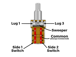
lindy dpdt pot.png


Now look at these two Seymour Duncan diagrams. The first is for a DPDT series parallel as the Volume....the second pic is with the DPDT pot series parallel as the Tone. The wiring for the humbucker seems the same expect the pot seems flipped 180 degrees in the second diagram.
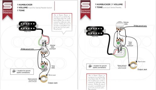
SD3.jpg

What I want to know is which lugs are which on these diagrams when compared to the Lindy Fralin photo. Which is lug 1? or Which is connection A or B? That will help me finally understand which connections go where when i look at any diagram. Thanks!
 
Last edited:
Re: Help Understanding DPDT Diagrams

The 2nd Duncan diagram is oriented the same as the Fralin. The 1st Duncan Diagram is upside down. Typically, the contacts closest to the pot body are "made" when the knob is pulled.
 
Re: Help Understanding DPDT Diagrams

So for the sake of my understanding...allow me to follow up.

In the 2nd Duncan diagram the red humbucker wire is going into Lug B as shown on the Fralin diagram? And the green wire is going into Lug D? Also, is which lug number is connecting that Tone pot to the Volume pot?

Sorry to need it dumbed down so much for me. Again Im new to this.
 
Last edited:
Re: Help Understanding DPDT Diagrams

In the 2nd Duncan diagram the red humbucker wire is going into Lug B as shown on the Fralin diagram? And the green wire is going into Lug D? Also, is which lug number is connecting that Tone pot to the Volume pot?

Yes. And the cap connects to middle lug of the pot and ground.

Sorry to need it dumbed down so much for me. Again Im new to this.

No prob. Glad to help.

And to elaborate . . . in the 2nd diagram, the contact pairs B & C and E & F are shorted, which shorts the red & white together for series mode. When pulled, A & B connect red to black, and D & E connect white to green. (Parallel mode.)
 
Last edited:
Re: Help Understanding DPDT Diagrams

Yes. And the cap connects to middle lug of the pot and ground.


No prob. Glad to help.

And to elaborate . . . in the 2nd diagram, the contact pairs B & C and E & F are shorted, which shorts the red & white together for series mode. When pulled, A & B connect red to black, and D & E connect white to green. (Parallel mode.)

I totally understand now. Thanks so much again for the help.
 
Re: Help Understanding DPDT Diagrams

Good lord did I have the same problem when wiring my strat a while back. Thanks for making the thread (searchable) to help others in the future
 
Back
Top