Questions about my 'Do It All' Wiring

The pdf you posted doesn't work as described. I built both the parrell and series diagrams as offered in that thread, both have undesirable results, at least to my ears. Here is a video of the wiring I just built, and I think it is pretty good. https://youtu.be/HYcZ3yZu9Xo

There are 3 different finalized diagrams in this thread. Which one are you talking about?

Also, 1 of them (the very first one in like post 1 or 2) only works if you have a RWRP pickup. The later two diagrams (in posts 64 and 76) only work if you have a pickup that has a mag flip only (i.e. NOT also reverse wound). So like said in the movie Indiana Jones and The Last Crusade: "Choose wisely".
 
Last edited:
Found it! Bumping this so I can share the info here.

I'm trying to troubleshoot my own guitar and I seem to be having trouble with getting the correct coils in positions 2 and 4.
 
Ok. Pretty sure this is it. Jack . . . check me out. ;)

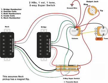
OK, while this project worked very well for my Warmoth, which is why I started this thread, I am trying it on my Brian Moore superstrat. This does not have a rw/rp neck pickup like my Warmoth did, but rather one with just a flipped magnet (I believe, since it was awhile ago).

So, to recap, what I am going for is:
1. Bridge
2.Outer coils of both humbuckers (in phase and hum-cancelling)
3. Both humbuckers
4. Inner coils of both humbuckers (in phase and hum-cancelling)
5. Neck

Wiring it up with the above diagram I am currently getting:

1. Bridge pickup
2. Outer coil of bridge humbucker, with both coils of neck
3. Both humbuckers
4. Inner coil of neck humbucker
5. Neck humbucker

How should I modify the diagram above to get 2 & 4 to work properly? Man, I need a Hyperswitch for this stuff!

What makes this especially frustrating to work on is that there is a piezo pickup in the bridge, as well as a 13pin Roland synth output as well (and 9v power supply for those).
The piezo and synth electronics are separate from the magnetics, so the wiring shouldn't involve those. But there is all kinds of ribbon cable in the way, so it is frustrating to work on.
 
I'm pretty sure this is it. I'll explain a couple details in the next post, since I can't edit when there's a pic.

Mincer_new.png
 
This assumes mag flip on the neck. If it's on the bridge, no prob. I'll come back to that. When you do the mag flip, you also need to "reverse" the wiring, to bring it back into phase. So, the colors for the neck pup are, from top to bottom, (in case the diagram isn't clear), red, bare, black, green, white. Then the red/green jumpers on the superswitch revert to parallel lines rather than an "X."

The reason it won't hurt if the mag flip is on the bridge, is that simply means both pickups will have reverse "absolute" phase, or polarity, which doesn't matter on a guitar.

Make sense?
 
The mag flip would be on the neck. So, essentially, it is like the first diagram. This is what I was thinking, too, so thanks for confirming. I really appreciate your help here.
 
OK I got it working!

Well, almost. The Superswitch's bridge position needs more room to switch. I can either modify the slot or the switch. So I will dremel a little of the switch so it can click into place.
 
That's odd. I've never seen a superswitch whose movement didn't mimic a regular 5-way.

It is weird. The slot in the wood is like 1 or 2 mm too short for the full throw of the switch. I was wondering why I could access the bridge pickup alone when the switch wasn't screwed in, but not when it was mounted. I think I can just carve out a small amount of metal on the switch to make it work.
 
It is weird. The slot in the wood is like 1 or 2 mm too short for the full throw of the switch. I was wondering why I could access the bridge pickup alone when the switch wasn't screwed in, but not when it was mounted. I think I can just carve out a small amount of metal on the switch to make it work.

If you loosen the screws that hold the switch in, is there any play to set it more centered so you get the full throw? Is this in a pickguard, or the body?
 
If you loosen the screws that hold the switch in, is there any play to set it more centered so you get the full throw? Is this in a pickguard, or the body?

No pickguard. It previously used a Megaswitch, and it seems like the 'shoulder' on the bridge side of the switch was ground down a bit to make it work. I don't want to modify the wood, and the holes in the wood for the mounting screws have no wiggle room at all.
 
I took a Dremel to the switch, not the body. I shaved off the shoulder on one side of the switch shaft, and that was enough for it to click into place. It was off maybe 2mm at the most. But it wasn't clicking into place, and I couldn't figure out why that position was the same as the one before it. Turns out that it didn't click into position...I felt the switch hit the wood, not click into place.
 
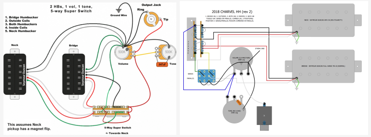
Hey guys! Sorry for reviving this thread, but his seems to be exactly what I needed. I have a HH Charvel with a 5 way super switch and an ON/ON series;parallel switch. I'm swapping pickups and I'm planning on using the diagram posted a few pages back to do it. The thing is, I'm not sure if I need to adapt any connections to include the switch. Would you be able to tell me if this makes sense?

Here's the diagram from this thread and the original Charvel diagram:

WIRING_HH.png - Click image for larger version  Name:	WIRING_HH.png Views:	0 Size:	149.4 KB ID:	6292560

And here's my initial plan, trying to mix the two diagrams together. Is this right? Am I dumb? Let me know!

5way+switch.jpg - Click image for larger version  Name:	5way+switch.jpg Views:	0 Size:	77.9 KB ID:	6292561
 
Last edited:
Back
Top