You are using an out of date browser. It may not display this or other websites correctly.
You should upgrade or use an alternative browser.
You should upgrade or use an alternative browser.
Wiring question 3 single coils
- Thread starter orpheo
- Start date

I actually have Type 2 in house, but I'm going to be using a 3 way rotary switch in this particular guitar for the phasing wiring. The 3 position rotary is a 4 pole as well, just laid out differently, but I can "translate" the schematic of the Type 2 for my rotary, that's not difficult at all. I'm just stumped by this phase idea that I'm having haha
Artie
Peaveyologist
Ok, so I drew the initial switch with two colors for a reason. The green is one DPDT switch, and the blue is a 2nd DPDT switch contained in one housing, with one switch upside-down from the other. Flipping the handle down operates the blue section, and flipping the handle up, operates the green section.
Sidenote: The type 2 is the preferable switch because it's symmetrical. In other words, it doesn't matter which way you turn it in the guitar. The type 1 is not. Once you measure the position of the contacts you need to mark the top with a Sharpie or something so you orientate it properly in guitar.
So here's how you'd wire the toggle: (I'll draw the rotary version in the next post.)
Artie
Peaveyologist
One more note. A phase switch comes last after any and all other switching you do, (series, split, parallel), but before the output switch, (3-way, 4-way, 5-way, toggle).
Also, it won't work well with a 2-conductor pup, or one that has a grounded cover, (Tele neck), or grounded baseplate, (several Tele and Strat singles).
Also, it won't work well with a 2-conductor pup, or one that has a grounded cover, (Tele neck), or grounded baseplate, (several Tele and Strat singles).
I figured that last part out the hard way. I wired up a phase switch on a tele with grounded covers. The covers were connected to the ground wire and/or the baseplate, and that shorted out everything. I called BKP (they made these pickups) and I have to decouple the pickups.
I'll draw out what I have in mind, and let you judge my work.
As far as I can tell, what I want is basically a phase switch but with an extra jumper added. That makes sense.
I'll draw out what I have in mind, and let you judge my work.
As far as I can tell, what I want is basically a phase switch but with an extra jumper added. That makes sense.
.png")

I tried to make my own wiring.
The idea is that I have 3 singlecoils in 1 guitar. Neck and bridge go through a series/parallel switch, and then to a regular 3 way selector toggle. That output goes to a 4 way rotary switch, where I can choose to have that signal on its own, series or parallel with a middle pickup, or the middle pickup on its own.
Plus, the phase rotary switch. I drew them in here as A and B, and the blue line is a jumper, as per your schematic.
Will this work? The 4 position rotary is just like the 4 position CRL switch, so this should be just that as well, but as a rotary instead of a lever switch.
If this works, I get all the options I need, in a clear, clean package (where I don't need to mess with routing out a 5 way blade in an existing guitar).
Here's the rotary. I'm assuming that the rotary is configured as two wafers. If it isn't, post a pic. Note that the two wafers are wired slightly different. Rotary in the middle, both in-phase. Click one way to reverse one, and click the other way to reverse the other.
I think this is it indeed! Mind giving my handiwork a look-through? To see if I missed anything? forget that I gave Mid and bridge the phase switch as a toggle, it's just for convenience' sake right now, and rotary or toggle won't change anything I think.

Artie
Peaveyologist
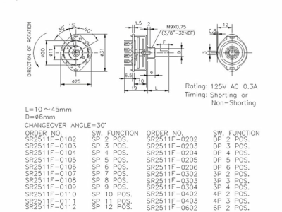
Can you clarify what your rotary switch is? I thought it was a 3-position. (A pic would be great.)
The 3 position rotary is a 4 pole as well, just laid out differently . . .
Last edited:
Can you clarify what your rotary switch is? I thought it was a 3-position. (A pic would be great.)
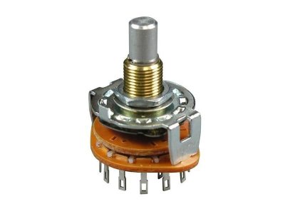
i have 2 rotaries coming in. one is a 4 way, the other is a 3 way.
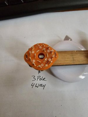
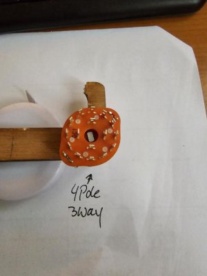
here are pics of the 3 way rotary and the 4 way rotary.
Attachments
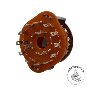

Your 3rd pic, (rear of the switch), won't work. That's a 3-pole, 4-position. You need the opposite. 4-pole, 3-position.
Highlighted in yellow.
I have both. one is 3 position 4 pole, the other is 4 position 3 pole.
Artie
Peaveyologist
I have both. one is 3 position 4 pole, the other is 4 position 3 pole.
3-pos, 4-pole is the one you'd need for my diagram. But we need to make sure we're on the same page first. Let me get back to you in just a bit.
Artie
Peaveyologist
I am aware. I have 3 position 4 pole ordered for the phase, and a 4 position 3 pole for the other rotary wiring.
Somewhere in the back pages, I think we're meandering in two different directions. But I gotta give my brain a rest. Let me look at this again tomorrow to make sure I'm on the same page as you.
I got the rotary switches in.
I have two rotaries. 1x 3way4pole, 1x4way3pole.
I want to use the 3way for the phase, and the 4 way in the wiring I drafted myself a few days ago. I just have no idea if it works. My idea was this.
I have 3 singlecoils. Bridge and neck are hooked up to a regular 3 way toggle (bridge, bridge and neck, neck), with a series/parallel switch so I can have bridge and neck in series or parallel.
The signal from the 3way toggle goes to a 4 way rotary, with the middle pickup, so I can have:
position 1) whatever comes out of the 3 way toggle (bridge, neck, series, parallel, in or out of phase, doesn't matter)
position 2) whatever comes out of the 3 way toggle but parallel with the middle pickup
position 3) whatever comes out of the 3 way toggle but in series with the middle pickup
position 4) middle pickup alone
and then of course the phase switch(es) coming first before the bridge or middle pickups are hooked up to any other switch.
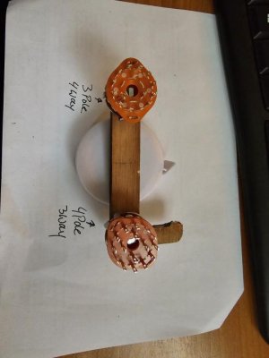
I added the photos of the rotaries below. I think my wiring could work, but I am not 100% sure.
I have two rotaries. 1x 3way4pole, 1x4way3pole.
I want to use the 3way for the phase, and the 4 way in the wiring I drafted myself a few days ago. I just have no idea if it works. My idea was this.
I have 3 singlecoils. Bridge and neck are hooked up to a regular 3 way toggle (bridge, bridge and neck, neck), with a series/parallel switch so I can have bridge and neck in series or parallel.
The signal from the 3way toggle goes to a 4 way rotary, with the middle pickup, so I can have:
position 1) whatever comes out of the 3 way toggle (bridge, neck, series, parallel, in or out of phase, doesn't matter)
position 2) whatever comes out of the 3 way toggle but parallel with the middle pickup
position 3) whatever comes out of the 3 way toggle but in series with the middle pickup
position 4) middle pickup alone
and then of course the phase switch(es) coming first before the bridge or middle pickups are hooked up to any other switch.
I added the photos of the rotaries below. I think my wiring could work, but I am not 100% sure.
Attachments
The pics help. Let me sip some coffee and get back on this.
Hey man, did you manage to check out my schematic? The one I drew up earlier in this thread?
Similar threads
- Replies
- 4
- Views
- 110
- Replies
- 13
- Views
- 384
- Replies
- 19
- Views
- 272