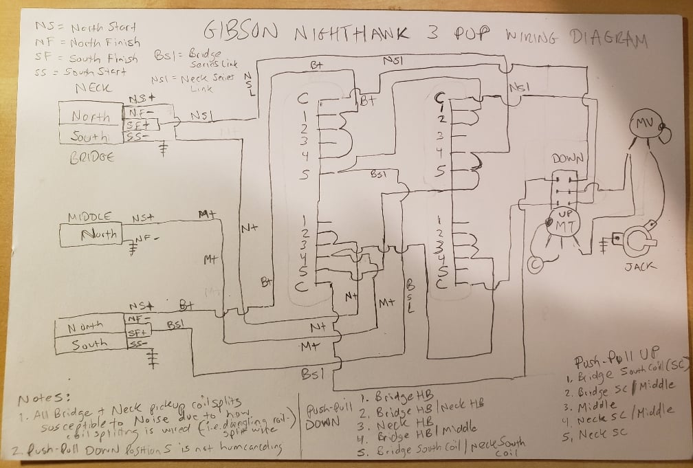
I noticed my '96 Gibson Nighthawk didn't sound quite right, and after a quick screwdriver tap test I found the neck pickup was shorting and activating in the bridge position (position 1 tone knob down) causing a muddy tone. I ordered a new fender SuperSwitch which feels 10x better than the 25 year old switch (along with a new Seymour Duncan bridge pup), but unfortunately I have gone through 4 attempts at wiring it with no success. At this point I am tempted to just go with a standard 5 way switch with basic coil splits, but I really love the "tele" position of the nighthawk in position 5 (tone knob down).

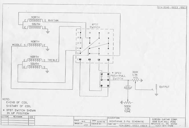
My question is can anyone translate the vintage superswitch wiring shown here from Gibson to a standard superswitch? Based on some other forums, I have also realized this diagram has the bridge and neck labels backwards.
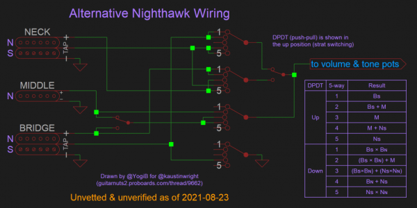
Here is an image I found online which has a modern switch, but it did not work at all after wiring it up twice. Based on the following forum, this also causes a floating coil rather than shorting it to ground so any other wiring suggestions are welcomed. https://forum.seymourduncan.com/foru...nt#post6105017

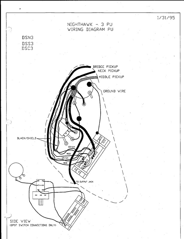
I can post photos of the Gibson switch later to show the connections, but for some reason I cannot find any info on this switch anywhere! As you can see in the Gibson wiring, it also has 2 lugs paired together at the top rather than the 1 isolated common on the modern one. I cant thank you guys enough, I am about to go bald from pulling my hair out on this one.
Also, on a side note I have always found "the tone knob down" layout to be quite confusing and was curious if anyone could work their magic to swap the pickup layout to the below configuration leaving the "tone knob up" position as-is. This is more intuitive in my opinion with positions 1, 3 and 5 being the full humbuckers and the 2 and 4 positions being the "in between" sounds. I would be perfectly fine with the original Nighthawk configuration, but figured I would throw it out there as my ideal situation. Thanks again for the help!

My question is can anyone translate the vintage superswitch wiring shown here from Gibson to a standard superswitch? Based on some other forums, I have also realized this diagram has the bridge and neck labels backwards.
Here is an image I found online which has a modern switch, but it did not work at all after wiring it up twice. Based on the following forum, this also causes a floating coil rather than shorting it to ground so any other wiring suggestions are welcomed. https://forum.seymourduncan.com/foru...nt#post6105017
I can post photos of the Gibson switch later to show the connections, but for some reason I cannot find any info on this switch anywhere! As you can see in the Gibson wiring, it also has 2 lugs paired together at the top rather than the 1 isolated common on the modern one. I cant thank you guys enough, I am about to go bald from pulling my hair out on this one.
Also, on a side note I have always found "the tone knob down" layout to be quite confusing and was curious if anyone could work their magic to swap the pickup layout to the below configuration leaving the "tone knob up" position as-is. This is more intuitive in my opinion with positions 1, 3 and 5 being the full humbuckers and the 2 and 4 positions being the "in between" sounds. I would be perfectly fine with the original Nighthawk configuration, but figured I would throw it out there as my ideal situation. Thanks again for the help!
Last edited: